Frustated Projects

Ad: This forum contains affiliate links to products on Amazon and eBay. More information in Terms and rules

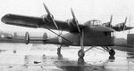
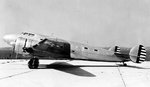
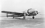
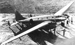
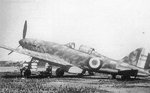
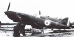
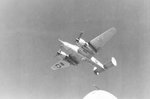
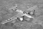
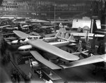
Airspeed A.S.39 Fleet Shadower designed as a maritime patrol aircraft in 1939, never reached production. The AS 39 was developed under specifications S.23/27 for a slow, long-range patrol aircraft for ultimate service with the Royal Navy. Specification S.22/37 was written around Operational Requirement OR.52, the type of aircraft envisaged was a 3 seater capable of operating from an aircraft carrier flight deck. It was built to a requirement for an aircraft capable of shadowing enemy fleets at night, that demanded a slow-flying, silent aircraft with a long range. A high-wing aircraft with fixed landing gear, an obervation post in the nose, and four small engines distributed along the wing to generate lift. There were 5 companies interested in this specification, Percival, Short Bros, Fairey, General Aircraft and Airspeed.

The AS 39 was a high-wing monoplane of mixed construction with the wings of wooden construction with two spruce and plywood box spars, former ribs, and a plywood covering. Sections between the spars were watertight to provide buoyancy in the event of a forced-alighting at sea. Wing bracing struts each consist of two steel tubes arranged in Vee formation. The fuselage is of metal construction with a detachable forward observer's compartment. The undercarriage consisted of a conventual fixed type. The AS 39 was powered by four 130 hp Pobjoy Niagara V seven-cylinder radial air-cooled geared engines, each driving a two-blade fixed-pitch wooden airscrew 8 ft. in diameter. The crew of the AS 39 consisted of a Pilot, observer and radio-operator.

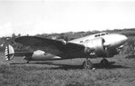
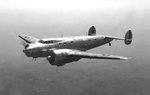
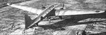
Two prototypes of the A.S.39 were ordered, N1323 and N1324, but only one was completed, N1323 being flown on 17/10/40, later than the GAL. 38 as it awaited the arrival of Niagara V's. In common with the GAL.38, the aircraft's performance during flight trials was disappointing due to aerodynamical problems, particularly when one engine was cut. In the end this aircraft like the GAL 38, no longer served a viable purpose.
 

Attachments

  • Airspeed AS-39 Fleet Shadower.jpg
    Airspeed AS-39 Fleet Shadower.jpg
    85.4 KB · Views: 588
In the summer of 1936, the Air Corps contracted for a single Lockheed Electra Model 10-A with extensive modifications. The plane, designated XC-35 by the Army, was intended for use as a high-altitude research and pressurized cabin test plane. As a result, the basic Electra fuselage was redesigned with a near circular cross section to better withstand the stresses of pressurization. Next, the large passenger windows were replaced with much smaller slit windows. The interior was split into two sections: the forward pressurized section had room for three crewmen and two passengers. The aft section, behind the pressure bulkhead had room for one additional passenger but could only be used at lower altitudes (below 12,000 feet). Besides the pilot and copilot, the XC-35 carried an engineer who controlled the pressurization and high altitude research equipment. The XC-35 was the world's first airplane specifically constructed with a pressure cabin.

The XC-35 was fitted with a pair of Pratt Whitney XR-1340 radial engines. These 550-hp engines were turbo-supercharged to deliver the necessary high-altitude performance. The plane was designed to fly at altitudes above 30,000 feet. The aircraft was delivered to Wright Field, Ohio, in May 1937. It was used in an extensive flight test program, and as a result, the Air Corps was awarded the 1937 Collier Trophy for the most significant aircraft development of the year.
 

Attachments

  • Lockheed XC-35 001.jpg
    Lockheed XC-35 001.jpg
    105.4 KB · Views: 562
  • Lockheed XC-35 004.jpg
    Lockheed XC-35 004.jpg
    56.1 KB · Views: 571
  • Lockheed XC-35 006.jpg
    Lockheed XC-35 006.jpg
    76.8 KB · Views: 536
  • Lockheed XC-35 002.jpg
    Lockheed XC-35 002.jpg
    59.5 KB · Views: 541
  • Lockheed XC-35 003.jpg
    Lockheed XC-35 003.jpg
    75.4 KB · Views: 550
  • Lockheed XC-35 005.jpg
    Lockheed XC-35 005.jpg
    86.9 KB · Views: 625
  • Lockheed XC-35 007.jpg
    Lockheed XC-35 007.jpg
    48.2 KB · Views: 560
The struggle of Regia Aeronautica to develop an effective bomber force was surprising for everyone, as in the pre-war period the Italian air force was highly rated and performed well during the Spanish Civil War and the Second Italo-Abyssinian War. But its performance in the first months of World War II was poor, even failing to reduce Malta with 1,000 bombers based less than 100 km (60 mi) away. One of the reasons was the lack of dive bombers and effective ground-attack aircraft; the Breda Ba.88 was a failure, and the Caproni Ca.310 was so ineffective that was replaced by the Fiat CR.32 fighter bomber. Another failure was the Savoia-Marchetti SM.85 dive bomber, phased out and replaced by the Junkers Ju 87 Stuka even before the evaluation of its successor the Savoia-Marchetti SM.86 was complete. In 1939, a new contest for a dive bomber was called, requiring a single-engine aircraft with a maximum speed of 500 km/h (310 mph), or 450 km/h (280 mph) if twin-engined, capable of carrying 500 kg (1,100 lb) bombs, with an endurance of 1,200 km (750 mi) with a single engine, or 2,400 km (1,490 mi) with two engines. There was only one twin-engine proposal, the Piaggio P.122, which despite its all-metal construction, dorsal-wing airbrakes, two Piaggio P.XI RC40 engines giving a total of 1,491 kW (2,000 hp), and the lack of competitors, was considered unfit for service. Single-engine types included the Caproni Ca.335 and the Breda Ba.201.

The Ba.201 was a single-engine dive bomber, all-metal in construction with a retractable undercarriage. It had a long fuselage, quite slim, with a high tail. The cockpit was set as far forward as possible. The wings had a distinct polyhedral "W" shape, like the Ju 87. The dive capabilities were found to be satisfactory, and the air brakes were highly effective, perhaps too effective - with the risk of slowing the aircraft down so much it became too easy a target. It was capable of carrying a single 500 kg (1,100 lb) bomb and was armed with two 12.7 mm (.5 in) Breda-SAFAT machine guns fixed in the wings. After such engines as the 895 kW (1,200 hp) Fiat A.38, the 716 kW (960 hp) Isotta-Fraschini IF L.121, and the powerful 839 kW (1,125 hp) Isotta-Fraschini Zetra, were evaluated, the Daimler-Benz DB 601 engine was chosen, because it was compact, and allowed free dives thanks to its direct injection system.

The prototype first flew on 3 July 1941, and was then sent to Guidonia for official testing. The aircraft showed that it had enough agility, once freed of its bombload, to hold its own against other Italian fighters. However speed was disappointing, only 460 km/h (290 mph) - slower than the requested for 500 km/h (310 mph) - and slightly slower than older front-line fighters. The aircraft was barely capable of defending itself against enemy fighters, and then only after releasing its bomb. It had very good forward visibility, but rear visibility was poor. In comparison the Junkers Ju-87D had a top speed of only 410 km/h (260 mph), but was armed with two new 7.92 mm (.312 in) MG 81z machine guns, with 3,200 rpm instead of 1,050. The Junkers rear-gunner gave it a greater defensive capability, while the Ba.201 pilot relied on himself alone. The Reggiane Re.2001 fighter bomber fitted with the same DB 601 engine was able to reach almost 550 km/h (342 mph), and carry 640 kg (1,411 lb) bombs. The first prototype MM.451 was followed by only one other before the programme was cancelled.
 

Attachments

  • Breda Ba-201 002.jpg
    Breda Ba-201 002.jpg
    117.3 KB · Views: 555
  • Breda Ba-201 001.jpg
    Breda Ba-201 001.jpg
    182.3 KB · Views: 591
  • Breda Ba-201 003.jpg
    Breda Ba-201 003.jpg
    108.2 KB · Views: 569
Developed from mid 1938 by Dmitrii L Tomashevich (one of Polikarpov's deputies), the I-180 was originally conceived with an all-metal structure. Limited all-metal construction experience, however, led the Polikarpov OKB to adopt an essentially similar structure to that of the earlier I-16, with a wooden monocoque fuselage and a fabric-skinned metal wing. The first prototype, the I-180.1, was powered by a 1,100hp Tumansky M-88 14-cylinder two-row radial, intended armament being four 7.62mm guns. This aircraft was lost as a result of engine failure during its first flight on 15 December 1938. The second prototype, the I-180.2, differed primarily in having a 1,000hp Tumansky M-87A (later M-87B) 14-cylinder two-row radial and lengthened wing outer panels. These increased wing span from 9.00m to 10.05m and area from 14.68m2 to 16.11m2. First flown on 19 April 1939, the I-180.2 was lost on its 53rd flight. A third prototype, the I-180.3 flown on 10 February 1940, featured a redesigned and more advanced wing structure, a 1,100hp M-88R engine, a cockpit canopy and an armament of two 12.7mm and two 7.62mm guns concentrated in the fuselage. Flown with both wheel and ski undercarriages, the I-180.3 was lost in an accident during State Acceptance Trials.

In the meantime, a pre-series of 10 aircraft based on the I-180.2 had been under construction as the I-180S (Seriyny or Series), the first three of these having been completed in December 1939. The I-180S was powered by the M-88R and carried an armament of two 12.7mm and two 7.62mm fuselage-mounted guns, and, like the I-180.3, featured an enclosed cockpit. The I-180S was cleared for service trials, but the results of these were somewhat academic as this fighter had been overtaken by the more advanced I-185. As a part of the I-185 development programme, one pre-series I-180S fighter had the dated triangulated pattern mainwheel legs replaced with legs of cantilever type, this aircraft being referred to as the I-180Sh, the suffix indicating Shassi (chassis). In the event, it was not completed and flown, the entire I-180 programme having meanwhile been abandoned.
 

Attachments

  • Polikarpov I-180 002.jpg
    Polikarpov I-180 002.jpg
    64.6 KB · Views: 558
  • Polikarpov I-180 001.jpg
    Polikarpov I-180 001.jpg
    85.1 KB · Views: 648
The aircraft that was eventually to be known as the Ki-77 was designed as a civilian long-distance record-breaking aircraft which would fly in the sub-stratosphere. It was hoped that its development would eventually lead to a future stratospheric transport aircraft. Work on the project began in March 1940, with further development being interrupted by the beginning of the Pacific War. Development resumed in the summer of 1942 under the designation of Ki-77, with the hopes that it could be used as a long-range communications aircraft that would help keep Japan in contact with the other Axis powers. Only two prototypes were completed, though they did achieve some unofficial speed records before the war's end.
 

Attachments

  • Tachikawa Ki-77 002.jpg
    Tachikawa Ki-77 002.jpg
    128 KB · Views: 541
  • Tachikawa Ki-77 001.jpg
    Tachikawa Ki-77 001.jpg
    108.2 KB · Views: 559
Developed by Kurt Tank in the mid-1930s, the Falcon was intended to compete against the Messerschmidt Bf 110. Originally intended to be powered by Daimler-Benz 600 series engines, the Falcon was nearly crippled by the RLM's requirement that the Junkers Jumo 210 series be used. Even so, during flight trials the Falcon showed itself to be 50 mph faster than the Bf 109B. Climb and Dive rates matched or exceeded the much-vaunted single-engine fighter with the Fw 187 being nearly twice the weight of the Messerschmidt fighter.

The Fw 187's initial role was to be a fast interceptor, however, requirements from the powers that be dictated that the Falcon be a destroyer. This dictated that a second crewman be added, this not occuring until the third prototype was built. Chronically underpowered, the addition of the second crewman as well as several other dictated changes caused the Falcon's performance began to suffer. Additionally, the Fw 187 did not mount a rear gun. This destroyer requirement doomed the Fw 187 and the RLM stuck with the Bf 110. The three production Falcons were used by Fock Wulf in thier factory defense squadrons, flown by test pilots, until Winter 1940 when they were sent to Norway. There they were unofficially evaluated by service pilots who preferred them to thier current Bf 110's. In 1943 the Fw 187 was considered for the night fighter role, but it's narrow fuselage did not allow the fitting of the necessary radar and equipment. Regardless, by this time Focke Wulf was engrossed with the development of the Ta 154 and the concept was shelved.
 

Attachments

  • Focke Wulf Fw-187 Falke.jpg
    Focke Wulf Fw-187 Falke.jpg
    127.9 KB · Views: 556
The initial derivative of the VG 30, the VG 31, differed from its predecessor in having the radiator bath moved aft for CG reasons, and in having a smaller wing of 12.00m2. It was proposed to power this development with an 860hp Hispano-Suiza 12Y31 12- cylinder liquid-cooled engine, but the prototype was never assembled. The VG 32 reverted to the original wing and was powered by a 1,040hp Allison V-1710- C15 engine, but the prototype was captured by German forces at Villacoublay two weeks before its scheduled maiden flight in 1940. The first development of the basic design to fly was thus the VG 33, which commenced its test programme on 24 May 1939. A production contract for 220 examples was placed in September 1939, this contract eventually being increased to 1,000 machines, but only 19 had been completed by the Chantiers Aero-Maritimes de la Seine by the time France collapsed. The VG 33 carried an armament of one 20mm Hispano-Suiza 404 cannon and four 7.5mm MAC 1934 M39 machine guns, and was powered by an 860hp Hispano-Suiza 12Y31 engine.
 

Attachments

  • Arsenal Vg-33 (Francia) 002.jpg
    Arsenal Vg-33 (Francia) 002.jpg
    134.7 KB · Views: 536
  • Arsenal Vg-33 (Francia) 001.jpg
    Arsenal Vg-33 (Francia) 001.jpg
    62.9 KB · Views: 527
In October 1940, the British Air Ministry issued Specification S.12/40 to Supermarine and Fairey for a catapult-launched, amphibian, reconnaissance and spotter aircraft to replace the Supermarine Walrus and Supermarine Sea Otter. An order for three prototypes of Supermarine's aircraft was issued in April 1943. There was an interruption in design due to the necessity of moving the Supermarine design office, after the bombing of the facility at Woolston. Further delays were caused by the extensive wind tunnel testing that was needed and the change from a Rolls-Royce Merlin to the more powerful Rolls-Royce Griffon. Also, the design specification was changed in 1944 to a new requirement, S.14/44 (later S.14/44/2) - the role of the aircraft being changed from reconnaissance and gunnery spotting to Air-sea rescue. This change removed the four-gun turret the design had featured. The first prototype - Seagull serial PA143 - first took off on 14 July, 1948 from Southampton Water, flown by test pilot Mike Lithgow. The second aircraft - PA147 - flew in September 1949, and was used for carrier trials on HMS Ark Royal later in that year, during which it demonstrated the capability to carry five passengers.[3] Experiments were also carried out with rocket assisted take-offs. By the early 1950s, helicopters were taking over the air-sea rescue role. In 1952, the two completed prototypes and the partially built third aircraft, PA152, were scrapped.

The Seagull had an all-metal construction with a two spar parasol wing mounted on a pylon connecting it to the fuselage. The single engine, a Rolls-Royce Griffon drove contra-rotating propellers; radiators were mounted below the engine in the pylon. The rear of the pylon accommodated an observer's position with two windows. An eye bolt was fitted on the wing, behind the engine, so the aircraft could be easily lifted from the water by crane. The wings were fitted with slotted flaps and full length leading edge slats and could be folded for compact, ship-board stowage. They also had a variable angle of incidence, pivoting at the front spar and actuated by an electrically driven jackscrew attached to the rear spar. This arrangement reduced stalling speed and increased lift, allowing the aircraft to use a smaller wing – compactness being an important feature for a ship-borne aircraft. Supermarine had tested this arrangement in the Type 322 and its capability was demonstrated when test pilot Mike Lithgow flew a Seagull at only 35 miles per hour (56 km/h). In July 1950, a Seagull competing in the Air League Cup Race gained the air-speed record for amphibian aircraft over a 100-kilometre (62 mi) course, by flying at an average speed of 241.9 miles per hour (389.3 km/h).

The hull was a normal frame and longeron design with chines. The tailplane, carried on top of the fin, had a very large dihedral, with smaller fins mounted on its tips perpendicular to its surface. A third fin was later added to the centre after testing of the first prototype had revealed an instability in yaw. This was added to the second prototype while it was still being constructed. The undercarriage retracted into bays on either side of the fuselage and could be easily removed, saving 180 kilograms (400 lb) of weight when the aircraft was operating as a pure flying-boat. The Seagull was also fitted with an arrestor hook for carrier landings; mounting points for JATO rockets were located just above the wheel wells. The crew normally consisted of three. During air-sea rescue work, a Seagull would be able to accommodate a pilot, navigator and medic, plus up to seven survivors.
 

Attachments

  • Supermarine Seagull.jpg
    Supermarine Seagull.jpg
    108.1 KB · Views: 515
Beech Aircraft designed a high-performance tactical aircraft during the latter days of World War II. Outstanding performance held promise of a bright future for the aircraft, but lack of availability of engines delayed the program so that its single contribution was to enhance the reputation of Beech Aircraft. Designated the Beechcraft Model 28, the big, twin-tailed attack aircraft was known to the United States Army Air Force as the XA-38. It also was named the Destroyer and, more popularly, the Grizzly. The Beechcraft Model 28 combined the size of a medium bomber with the speed of the fastest propeller driven fighters of the day. It was highly maneuverable and could take off and land in an area considerably smaller than needed by other airplanes of a comparable size.

The XA-38 was a departure in attack planes, being built around a 75mm automatic cannon, which extended from the nose of the ship, giving the plane a most distinctive appearance. The aircraft carried a pilot and gunner and mounted six .50 caliber machine guns in addition to the cannon. It was designed as an attack plane with a primary mission of attack and destruction of tanks, armored vehicles, light surface vessels, ground installations and submarines by gunfire. A secondary tactical mission of bombing and laying smoke screens could be performed by externally mounting bombs, depth charges and chemical tanks. Empty weight of this twin-engine all-metal mid-wing monoplane was 23,230 pounds with a design gross weight of 29,900 pounds; however, various combinations of fuel, oil, external bombs, external long range fuel tanks and smoke tanks could be carried at gross weights up to maximum alternate gross weight of 36,332 pounds. Length of the plane was 51.7 feet and wing span 67.08 feet. Outside maximum width of the fuselage was 56 inches and maximum fuselage height 92 inches.

Every means possible was employed to decrease drag, including flush riveting of all exposed skin surfaces. A striking demonstration of the resultant speed was furnished the Army when it assigned one of its fastest fighters to pace the XA-38 for speed calibration tests and found the Beechcraft outdistancing the fighter. Despite these high speeds, the airplane at a gross weight of 31,250 pounds could land at low speed in a small area. The forward part of the fuselage had a steep slope downward permitting the pilot an excellent view downward and forward. Access to the pilot's compartment was through a hinged section of the cockpit enclosure and was reached from the upper surface of the wing. Cooling of the huge Wright Cyclone R-3350 engines was obtained from circular cowlings of the NACA type and careful design of the cowl entrance and exit, as well as by locating the exhaust stacks so that they augmented the flow of exiting air. Cooling was controlled by automatic cowl flaps operated by a control unit having a temperature element in the hottest engine cylinder.

Propellers were three-bladed, constant speed and full feathering, Hamilton Standard, with a minimum blade angle of 16 degrees and a maximum blade angle of 82 degrees as measured at the 72-inch radius. Wing air foil section was derived from NACA-2300 series, 18.87 percent thick at the root chord and 12 percent at the tip chord. The wings were of conventional all-metal construction with an area of 625.9 square feet. Taper ratio was 3.07 to 1; incidence 4.39 degrees at the root and 1 degree at the tip; dihedral, measured at the quarter chord point, 5 degrees and aspect ratio 7.19. For flight in icing conditions, leading edges were heated through internal air ducts and the entire surfaces of the wings were warmed by air discharged from the leading edge ducts and passed through the wing to the trailing edges.

The main spar was located at 25 percent of the wing chord and the rear spar at 75 percent of the wing chord. These spars were designed as the principal structural members resisting bending. Wing tips and outer panels were removable to facilitate fabrication and replacement. The center section was built in halves, joined together at the fuselage center line. Slotted type flaps extended over the span of the center section on each side, except for the portion enclosed in the fuselage. Ailerons extended from the outer panel joint to the removable tip. Control surfaces were conventional with ailerons, elevators and rudders aerodynamically, dynamically and statically balanced. Aileron area was 51.7 square feet, or 8.2 percent of the wing area with each aileron equipped with a balancing tab; the tab in the left aileron also acting as a trim tab controllable from the cockpit.

The dual vertical tail was similar in design to the twin-engine Beechcraft Model 18 series. Fins had an area of 33 square feet. Rudders had an area of 36. 8 square feet and were constructed with a formed aluminum alloy frame. Metal covered over the nose section. The chord of this balance area was increased somewhat near the top to provide additional balance area. Area of the horizontal stabilizer was 115 square feet, with a span of 230 inches and a maximum chord of 81 inches. Stabilizers had an area of 64 square feet and construction was two spar, skin and stringer. The elevator area was 50.9 square feet and was constructed with a formed sheet metal aluminum alloy frame. Fabric covered over the portion aft of the elevator spar, with an aluminum alloy sheet covering over the nose section.

Slotted-type flaps had a control system designed to prevent retracting the flaps at a rate rapid enough to cause the airplane to settle in a dangerous manner. Each flap had a span of 155.5 inches, and the plane had a total flap span of 372 inches. Average flap chord was 29.48 inches and area 63.8 square feet. Fuselage construction employed bulkhead rings and longitudinal stringers. Openings were reinforced by heavy stringers or box sections where extra rigidity was required. Fuselage construction was in four main sections to permit easy repair and replacement. The entire forward section of the nose was arranged on counterbalanced springs to open like the hood of an automobile and expose the 75mm cannon for servicing and replenishment of ammunition. The nose section, complete with cannon, could be removed and replaced with other nose sections equipped with other armament arrangements.

The landing gear consisted of two large main wheels and a full swiveling tail wheel. Both main wheels and tail wheel were retracted and extended by hydraulic means, with separate and completely independent hydraulic and pneumatic emergency systems. The auxiliary systems were independent of the main system up to, but not including, the actuating cylinders. Shock struts were of the oleo-pneumatic type. Wheel doors were operated mechanically through linkage to the landing gear mechanism. Main wheel doors opened while the wheels were extending or retracting and closed when the wheels were fully down or fully up. This feature minimized damage to the door structure due to buffeting. Following its first flight May 7, 1944, the airplane was flown to Eglin Field, Fla., where it underwent extensive Army tests. In these tests it established outstanding records for availability, for flight and for efficiency.
 

Attachments

  • Beechcraft XA-38 Grizzly 002.jpg
    Beechcraft XA-38 Grizzly 002.jpg
    83.8 KB · Views: 482
  • Beechcraft XA-38 Grizzly 001.jpg
    Beechcraft XA-38 Grizzly 001.jpg
    56.3 KB · Views: 486
  • Beechcraft XA-38 Grizzly 003.jpg
    Beechcraft XA-38 Grizzly 003.jpg
    100.4 KB · Views: 467
During WW2 Germany and Japan shared technology as demonstrated by a copy of the Daimler-Benz 601 inverted V engine showing up in the Ki-61 Tony. Other key items that were shared or attempted to be shared were pieces of turbo jet technology. At one point Germany tried to ship a complete Jumo 004 engine to Japan which fortunately never arrived. However a drawing and a few pictures of the BMW 003 turbojet engine did end up in Japanese hands. This was a crucial delivery. The Japanese military had not expressed any real interest in jet powered aircraft throughout most of the war until a Japanese emissary witnessed a demonstration of the Me-262 in Germany. This prompted development of a Japanese jet powered aircraft.

In 1944 Nakajima designers Kazuo Ohno and Kenichi Matsumura were tasked with creating a reconnaissance aircraft that would seat three crew members. As design work progressed it was discovered that the Japanese jet engine prototypes would not produce enough thrust to achieve the performance parameters. Even after several design improvements the results were not acceptable however it was at this point that the BMW 003 information came into their hands. Japanese engineers were able to manufacture a turbojet engine based on the BMW information with an excess of 1000 pounds thrust. Designated the Ne-20 this engine gave the program a critical boost and was used for the single seat prototype.

Three different versions of the aircraft were planned; a three place reccon aircraft, a two place bomber and a single seat day fighter with two 30mm cannons. All versions included folding wings to allow for concealment in caves. One single seat, unarmed prototype was completed and flown once before the end of the war. On its second attempt using RATOG bottles the take-off was aborted resulting in a crash that damaged the landing gear. Seems the technicians had not mounted the rocket bottles properly. It is a common misconception that the J9Y was a copy of the Me-262 but there is actually very little relationship other than they both had two turbojet engines slung under the wings and were jet aircraft. The J9Y was about 30% smaller than the 262 and did not have nearly the wing sweep. Ultimately Japanese turbo-jet technology had no effect on the war and simply became a historical curiosity. The single surviving example of the J9Y Orange Blossom is displayed at the Smithsonian in Washington D.C.
 

Attachments

  • Nakajima J9Y Kikka.jpg
    Nakajima J9Y Kikka.jpg
    94.4 KB · Views: 788
  • Nakajima J9Y Kikka 002.jpg
    Nakajima J9Y Kikka 002.jpg
    114.9 KB · Views: 489
The Fiat G.56 was basically a Fiat G.55 with a German Daimler-Benz DB 603 engine. Two prototypes were built, flight tests starting in March 1944. On 30 March, Commander Valentino Cus reached speeds of 690/700 km/h (430/440 mph). Official maximum speed was 685 km/h (426 mph) and the aircraft was armed with three 20 mm MG 151/20s, one firing through the propeller hub, the other two installed in the wings. While performance was excellent, the aircraft proving superior to both the Bf 109K and Bf 109G and Fw 190A, outmanoeuvring all types in testing, production was not allowed by the German authorities.
 

Attachments

  • Fiat G.56 Torino 001.jpg
    Fiat G.56 Torino 001.jpg
    105.6 KB · Views: 469
  • Fiat G.56 Torino 002.jpg
    Fiat G.56 Torino 002.jpg
    67.5 KB · Views: 459
  • Fiat G.56 Torino 003.jpg
    Fiat G.56 Torino 003.jpg
    40.1 KB · Views: 455
  • Fiat G.56 Torino 004.jpg
    Fiat G.56 Torino 004.jpg
    28.4 KB · Views: 461
The Ar 197 had its origin in the requirement for a fighter capable of operating from the planned (but never completed) German aircraft carriers Graf Zeppelin and Peter Strasser. The Ar 68H had been the first Arado aircraft to have a fully-enclosed cockpit, and was selected as a base design for the Arado Ar 197. The first prototype of the Ar 197, the V1, was based on the Ar 68H and featured a fully-enclosed cockpit, Daimler-Benz DB 600A inline engine, and three-blade propeller, but was not fitted for naval operations. The second prototype, the Ar 197 V2, was similar to the V1, but was powered by a BMW 132Dc radial engine, and was fitted with naval equipment including an arrester hook and catapult spools. Both the Ar 197 V1 and V2 flew in the spring of 1937. In the summer of 1937 a third prototype, the V3, was built. Powered by a more powerful BMW radial engine and was the first prototype fitted with weapons, the Ar 197 V3 was armed with two 7.92 mm (.312 in) machine guns and one 20 mm cannon. The V3 was also fitted with racks under the fuselage which could carry four 50 kg (110 lb) bombs, an auxiliary fuel tank, or a smoke-laying canister.
 

Attachments

  • Arado Ar-197.jpg
    Arado Ar-197.jpg
    94.6 KB · Views: 2,990
In 1927, the British Air Ministry, faced with the need to deal with increased bomber performance, issued Specification F.20/27 for a single seat interceptor. Unlike previous fighter Specifications, the resulting aircraft were intended to be short ranged (not intended to mount standing patrols), fast climbing high altitude aircraft, carrying a minimum of equipment. To meet this requirement, de Havilland developed as a Private Venture, the DH.77, designed by W.G. Carter, of Gloster Aircraft Company, in close collaboration with engine designer Frank Halford. The DH.77 was a small low-winged lightweight monoplane, of mixed metal and wood construction, powered by a 300 hp (224 kW) Napier Rapier air cooled H-engine, which offered very low frontal area to minimise drag. The wing was braced with distinctive bracing struts above the wing, while the aircraft had a wide track fixed tailwheel undercarriage. It was fitted with large span ailerons and a stabilator to give good control characteristics and spin recovery. Armament was the normal pair of synchronised Vickers machine guns, mounted on each side of the cockpit.

The single prototype first flew on 11 July 1929.Despite the low power of the Rapier (which gave only 60% of the power of the Rolls-Royce Kestrel which powered the competing Hawker Hornet), the DH.77 demonstrated excellent performance, reaching 204 mph (328 km/h). It was delivered to Martlesham Heath for evaluation by the Aeroplane and Armament Experimental Establishment on 12 December 1929. Although the prototype was purchased by the Air Ministry, no production followed, the orders going to the heavier and more powerful Hawker Fury, production version of the Hornet. The DH.77 continued in use at Martlesham until 1934.
 

Attachments

  • De Havilland DH-77.jpg
    De Havilland DH-77.jpg
    104.2 KB · Views: 478
During the Second World War, the German Reich Army was known for constructing war machineries that were either the heaviest or the largest to have domination over the skies. One of these machineries is the Blohm Voss Bv 238 which was considered to be the largest aircraft ever to be produced by any of the Axis powers of World War Two. The BV 238 was designed as a floatplane and it was intended to be the so huge to provide the German Army with additional loading capacity during WW2. Weighing at 54,000 kilograms, this WW2 German aircraft used six 1750 HP piston engines that were produced by the Daimler-Benz company. The engines, which were face forwarding, were installed on a high monoplane wing design. Each wing was mounted with three engines each.

The first prototype of the BV 238 saw flight in 1944 and had shown great potential as a floatplane. This WW2 aircraft showed excellent performance because it carried a large payload and had tremendous range and speed for an aircraft of that size. Had the BV 238 been produced in full-scale, the German Army would have had an excellent floatplane in their arsenal of aircrafts. However, only one BV 238 was ever completed during WW2 and this prototype was sunk while it was being docked and repaired on Lake Schaal in 1944. The planes responsible for the sinking of the only mammoth BV2 238 were three P-51 Mustangs belonging to Allied Forces and which were led by Lt. Urban Drew. It was later found out that the BV 238 was still undergoing flight testing when it was destroyed and sunk. Besides being the largest aircraft to be produced during WW2, the BV 238 is also recognized as being the largest aircraft to be destroyed by an Allied Force pilot.
 

Attachments

  • Blohm  Voss Bv-238 V1 002.jpg
    Blohm Voss Bv-238 V1 002.jpg
    139.9 KB · Views: 462
  • Blohm  Voss Bv-238 V1 001.jpg
    Blohm Voss Bv-238 V1 001.jpg
    70.5 KB · Views: 460
The Blériot 125 (or Bl-125) was a highly unusual French airliner of the early 1930s. Displayed at the 1930 Salon de l'Aéronautique in Paris, it featured accommodation for twelve passengers in two separate fuselage pods. Between them, these pods shared a tailplane and a high wing. The centre section of wing, which joined the fuselage pods also carried a nacelle that contained an engine at either end and the crew compartment in the middle. When actually flown the following year, it displayed very poor flight characteristics and although attempts to improve it continued on into 1933, certification could not be achieved and the sole prototype was scrapped the following year.
 

Attachments

  • Bleriot 125.jpg
    Bleriot 125.jpg
    121.2 KB · Views: 487

Users who are viewing this thread

Back