Vic Balshaw
Major General
Both sides look brilliant George, you should be pleased. 

Follow along with the video below to see how to install our site as a web app on your home screen.
Note: This feature may not be available in some browsers.
Ad: This forum contains affiliate links to products on Amazon and eBay. More information in Terms and rules
Wheel well reinforcement strips which were later added to the inside of the wheel well. Not sure when the change was madeSorry Fubar,
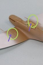
I wanted to ask about a particular feature on your model that reproduces two rails on both wings.
I was wondering what they were and if they are present on all the Mk V's.
Thank you Berny


Sorry Fubar,
I wanted to ask about a particular feature on your model that reproduces two rails on both wings.
I was wondering what they were and if they are present on all the Mk V's.
Thank you Berny
Wheel well reinforcement strips which were later added to the inside of the wheel well. Not sure when the change was made
Do you mean the two reinforcing strakes over the wheel bays? If you do, these were introduced as a repair kit for older aircraft that showed signs of the matal fatique in this area. Later these were moved to the wheel bay interior. So no matter where a Spit serviced but if there were the damages to the wing skin.
Thank you Wurger.IIRC the stiffeners appeared in October/November 1941. As I have mentioned it in the another thread ( see the quotation above ) the strengthening strakes were attached to these Spits that showed the damages to the metal skin there. Therefore these were retrofitted to the early models as well. Regarding the Spitfire Mk.V there were three mods regarding the reinforcing of the wheel-well top skin, the Mod 455, 529 and 532. None of them stated what kind of the exact modification it was. Anyway the Mod 455 was incorporated 10 October 1941.
 to remember it.
 Just to belabour the point, the sketch posted by Wojtek in the GB62 intro thread shows the IFF antenna wires. Not 100% proof but indicates they were probably present:
View attachment 783516
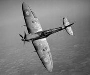
Beauty. Everything in the kit but the mast will need slight modification. The aircraft was damaged during the Operation Jubilee. Damage included the area in front of the fin so I'm thinking a more modern fin flash was installed and possibly the fuselage roundels as well