There is a massive difference between making one engine that will run for a few hours and making thousands of engines all of which will operate under all foreseen conditions for hundreds of hours. Napier didn't have the knowledge of metallurgy or production engineering let alone the equipment, the fault is as much with those awarding the contract as those bidding.I agree totally.
According to LJK Setright, Napier had been "living hand to mouth for years" and a lot of the Sabre's problems were due to the fact that the production models could not compare to the hand built prototypes. Apparently their factory in London was full of antique lathes etc.
Navigation
Install the app
How to install the app on iOS
Follow along with the video below to see how to install our site as a web app on your home screen.
Note: This feature may not be available in some browsers.
More options
You are using an out of date browser. It may not display this or other websites correctly.
You should upgrade or use an alternative browser.
You should upgrade or use an alternative browser.
Leading edge shape on German fighter aircraft?
- Thread starter spicmart
- Start date
Ad: This forum contains affiliate links to products on Amazon and eBay. More information in Terms and rules
More options
Who Replied?Shortround6
Lieutenant General
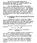
Napier was coasting on the reputation of the old Lion engine.
While the Rapier, Javelin and Dagger got a fair amount of press they weren't going to keep the company solvent.
The 16 cylinder Rapier was an expensive way to get under 400hp and only powered just over 70 planes (only one a multi engine)
The Javelin inline 6 was built in tiny numbers and didn't offer much that couldn't be done by DH Gypsy 6
The Dagger wasn't exactly a rousing success either. Both operationally and in sales it left something to be desired. The Sabre in the late 30s was probably Napiers last gasp. Had war taken a few years longer to break out Napiers might have closed their doors much sooner.
A short pdf on airfoils, https://www.nasa.gov/sites/default/files/atoms/files/hallion.pdf
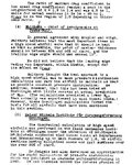
Why did the Germans use NACA airfoils when they had their own airfoil designs, Gottingen?
The Gottingen airfoils were extremely significant.
If you look at wing profiles from Otto Lillienthal through to the Wright brother to ALL allied fighter aircraft through world war one you will notice that they are only 4% thick, slimmer than a supersonic fighter.
The Germans were the first to realize that thick airfoils (greater than 10%) are much better. They had nearly twice the lift coefficient of thin sections. They were used on the Fokker Triplane and Fokker DVIII and so these aircraft and so these aircraft had much higher climb rates and smaller turning circles than allied aircraft. The fighters the Germans were about to produce just before the armistice would have trounced any allied fighter.
What had happened is this. Hugo Junkers was inspired to develop all metal monoplanes. He didn't like the idea of struts and braces holding the wings up so he investigated thick airfoils that were thick enough to carry the big strong spars needed.
The results delighted him and Junkers built no only the first all metal aircraft but the first unbraced monoplane.
Anthony Fokker essentially stole the Junkers information and ideas and the rest his history.
The AVA at Gottingen had Betz and Prandle (who had developed the boundary layer and lifting line theory) understood what had happened straight away.
Wing sections were being tested subscale. However because of Reynold effects the boundary layer is different. Put it this way, if boundary layer is laminar for 1cm then it is laminar across a bees wing which can be very thin and flat. However 1cm across a sub scaled model is maybe 10% but is insignicant on a full wing.
The Gottingehn series were thus the first modern airfoils. They were widely copied until the NACA series took overs as a resutt of the NACA massive investment.
German researchers were moving on to swept wings, laminar flow wings, boundary layer suction (flown on test beds) which would have been used on the second generation of German jets. Its really a matter of timing the Germans didn't get a laminar flow wing in service though it can be argued the sections used on the Me 262 and Ar 234 were exactly that.
Last edited by a moderator:
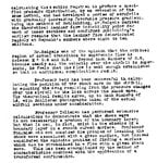
NACA airfoils were derivatives of many of the German WWI designs but into the 30's the NACA was leading the way in high Reynolds number wind tunnel experimentation/validations - notably in cambered and reflex cambered airfoils to investigate changes to CL and Pitching Moment CM as function of AoA.
In the 1920s and 1930s the US had the money. The Germans were the first to realise the effects of Reynolds numbders and the first to develop thick airfoils which were used on the Junkers monoplanes and 'stolen' by Fokker on their famous DVII!and Triplane. They had nearly twice the CLift of the thin airfoils used during WW1.
Two "German" researchers Max Munk (Zeppelin) and Theodore von Karman (junkers employee) came to the US and were employed by the NACA.
It was Munk who pushed to get the variable density wind tunnel built. It was this pressurized tunnel that allowed the NACA to systematically and rapidly build and airfoil data base under Eastman Jacobs who gave use the NACA 4 digit, 5 digit that laminar wing.
The NACA work was brilliant. The Germans were moving on to swept wings, laminar wings (on their own), boudary layer control (Tollman Schictling) and even super critical wings. The 1943 super critical wing developed in Germany got Airbus out of a patent suit with Boeing.
It would be stupid to waste wind tunnel time reinventing the wheel.
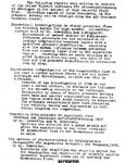
Here are a few American and British aircraft with Gottingen airfoils. They seemed to be good for flying boats.
If you had the equal of $10,000 in today's money you could fly one of these to Honolulu and on to China.
Martin China Clipper.
Last edited:
No idea why they all thought that the leading edge wasn't that important
Attachments
-
 IMG_20171204_210933.jpg127.4 KB · Views: 158
 -
 IMG_20171204_211206.jpg109.2 KB · Views: 157
 -
 IMG_20171204_211220.jpg79.9 KB · Views: 175
 -
 IMG_20171204_211000.jpg110.4 KB · Views: 192
 -
 IMG_20171204_211010.jpg106.1 KB · Views: 176
 -
 IMG_20171204_211022.jpg128.3 KB · Views: 169
 -
 IMG_20171204_211035.jpg121.7 KB · Views: 139
 -
 IMG_20171204_211047.jpg139.1 KB · Views: 149
Aeroweanie
Airman 1st Class
- 131
- Jan 17, 2021
This is an old thread, but I think worth reviving.
Thank you tomo pauk for the correction on the F4U - I've fixed my master database and will push it to UIUC soon.
On a related note, I'm trying to track down the designation of the LB laminar flow airfoils used on the Mitsubishi G4M2. Does anyone have this information?
Thank you tomo pauk for the correction on the F4U - I've fixed my master database and will push it to UIUC soon.
On a related note, I'm trying to track down the designation of the LB laminar flow airfoils used on the Mitsubishi G4M2. Does anyone have this information?
On a related note, I'm trying to track down the designation of the LB laminar flow airfoils used on the Mitsubishi G4M2. Does anyone have this information?
I'll humbly call
")
Not so much detailed but the basic airfoil for the G4M2 was called Mitsubishi No.357 aka MAC-357(max thickness 15% at 40% chord) based on Dr. Ichiro Tani's study.
Dr. Tani's study

Actual section

Source: https://livedoor.blogimg.jp/fw190d2dora-mokei/imgs/2/1/21c1b35b.jpg
Dr. Tani's study
Actual section
Source: https://livedoor.blogimg.jp/fw190d2dora-mokei/imgs/2/1/21c1b35b.jpg
drgondog
Major
Note that F4U had three airfoil 1.( NACA 23018 from Root to wing fold for gull wing, 2.), NACA 23015 for main wing section and 3.) NACA 23009 for tipThis is an old thread, but I think worth reviving.
Thank you tomo pauk for the correction on the F4U - I've fixed my master database and will push it to UIUC soon.
On a related note, I'm trying to track down the designation of the LB laminar flow airfoils used on the Mitsubishi G4M2. Does anyone have this information?
Aeroweanie
Airman 1st Class
- 131
- Jan 17, 2021
Thank you both Shinpachi and drgondog!
On the F4U, I should have caught it, as I've long relied on the Paul Matt drawings:

Why? For this:

On the F4U, I should have caught it, as I've long relied on the Paul Matt drawings:
Why? For this:
drgondog
Major
Interesting Dave - can I assume from the drawings of the airfoils that there was no washout?Thank you both Shinpachi and drgondog!
On the F4U, I should have caught it, as I've long relied on the Paul Matt drawings:
View attachment 736426
Why? For this:
View attachment 736427
Aeroweanie
Airman 1st Class
- 131
- Jan 17, 2021
Interesting Dave - can I assume from the drawings of the airfoils that there was no washout?
Yes, there appears to be no geometric twist
drgondog
Major
Interesting, save a little induced drag and perhaps decrease enough roll authority at 80+kts on carrier approach to earn Ensign Killer.Yes, there appears to be no geometric twist
I now wonder how F6F set up? That said, IIRC the primary issue was inboard left 'gull' wing section stalled out due to prop vortex upwash - so they installed a small spoiler under right gull wing section to accelerate inboard stall?
Aeroweanie
Airman 1st Class
- 131
- Jan 17, 2021
Interesting, save a little induced drag and perhaps decrease enough roll authority at 80+kts on carrier approach to earn Ensign Killer.
I now wonder how F6F set up? That said, IIRC the primary issue was inboard left 'gull' wing section stalled out due to prop vortex upwash - so they installed a small spoiler under right gull wing section to accelerate inboard stall?
It was probably done that way for ease of production.
The NACA reports on the F6F don't mention wing twist. In addition, I have a really good CAD model of it, built off the Grumman drawings, and it has no twist.
Does the gull wing design act in a similar way to geometric twist?It was probably done that way for ease of production.
The NACA reports on the F6F don't mention wing twist. In addition, I have a really good CAD model of it, built off the Grumman drawings, and it has no twist.
Aeroweanie
Airman 1st Class
- 131
- Jan 17, 2021
Shinpachi-san,
Do you have any information the Mitsubishi B-9 airfoil, used on the Ki-51 (and I think the Ki-21)?
Do you have any information the Mitsubishi B-9 airfoil, used on the Ki-51 (and I think the Ki-21)?
don4331
Senior Airman
Pardon me if it has been answered elsewhere, but is there any wing twist on the F4F?It was probably done that way for ease of production.
The NACA reports on the F6F don't mention wing twist. In addition, I have a really good CAD model of it, built off the Grumman drawings, and it has no twist.
I'm surprised that your pressure model doesn't show any (or at least not significant) pressure change as a result of the gull wing - I'm filing under learned something new.
Adding twist is really a one time issue for production isn't it? Once forms and jigs are set up, its not significant - wing skins are more/less 2D still. Ellipse form/rounded wingtips are different beast, but again American stamping technology should be up to the task if designer finds it necessary.
Aeroweanie
Airman 1st Class
- 131
- Jan 17, 2021
Pardon me if it has been answered elsewhere, but is there any wing twist on the F4F?
I'm surprised that your pressure model doesn't show any (or at least not significant) pressure change as a result of the gull wing - I'm filing under learned something new.
Adding twist is really a one time issue for production isn't it? Once forms and jigs are set up, its not significant - wing skins are more/less 2D still. Ellipse form/rounded wingtips are different beast, but again American stamping technology should be up to the task if designer finds it necessary.
I don't see mention of any geometric twist in the F4F wing in any of the specifications I have.
There probably is an impact of the gulling on the wing pressure distribution, but you just can't see it in that image.
I'm not a manufacturing guy, but I know that they complain about the difficulty in building twisted wings.
drgondog
Major
Dave - did you look at high AoA/CL for the wing/body?I don't see mention of any geometric twist in the F4F wing in any of the specifications I have.
There probably is an impact of the gulling on the wing pressure distribution, but you just can't see it in that image.
I'm not a manufacturing guy, but I know that they complain about the difficulty in building twisted wings.
I tried thinking about it and ended up needing a darkened room and some tablets.Dave - did you look at high AoA/CL for the wing/body?
Users who are viewing this thread
Total: 1 (members: 0, guests: 1)