Maneuverability vs Speed

Ad: This forum contains affiliate links to products on Amazon and eBay. More information in Terms and rules

I wanted to save time twenty years ago when I started 3D modelling but the finished work always told me how less time I spent for it. However, if you want to be a professional modeller, you should think of it first IMO.
In my case, I did not want to save time for my work after all :)

A6M5_Taic.jpg
 
Procrastination is a bad habit of mine, and time is only part of my worries. The tutorial I am referring to involves the creation of a simple, low-end model, and I, at least in the past, had the sole goal of making lightweight models that could be placed into older computer games without much hassle. However, both of my models, even in their unfinished states, have a relatively high amount of triangles between them, if only because I have the urge to keep adding more detail. They look awful otherwise.
 
That tip will certainly be useful, particularly for small details. My models were not intended to be seen up close however, as they were initially made with a classic strategy game in mind, though my goals have shifted to some degree since then. I had larger details in mind, like the overall contours of the plane's outline.

This comparison, between the tutorial I'm following and my incomplete model, should provide some insight into my line of thought:

tutorialplanevertstabil.jpg

simplef6fvertstabilwip.png

Have yet to narrow the vertical stabiliser.
tutorialplanewing.jpg

He deviates little from this basic shape.
simplef6fwingwip.png

I skipped a step to work on the wing. The model's unfinished, and the tip of the wing has yet to be added. I'm not confident at all, and I don't really know what I'm doing anymore. I would still say that my wing, even while a work in progress, is still somewhat more detailed and slightly more precise, though attempting such leads to more faces and triangles. I'm aiming for no more than 2000 triangles in total.

As a disclaimer, I was using the tutorial as a basic starting point of sorts, and never intended to slavishly follow it.
 
Last edited:
Or -
E to extrude outer vertices to form wingtip section
M to merge in each center

The tutorial says "Alt-M" but does not function in Blender 3.6.1 LTS.

64005.jpg
64006.jpg
 
n
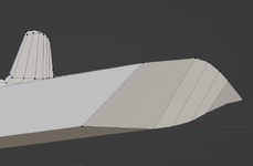
One thing that made the Zero so manuverable was that the tip wasn't a flat edge. It swept upwards, towards the leading edge.
This made the tip act like a little wedge and it helped the plane roll just a little faster.
The wing tip doesn't sweep upward toward anything. It follows the leading edge's washout seamlessly. The edge of the wingtip is rounded, just like the leading edge. In the A6M5 Model 52, it rolls slightly better due to slightly reduced span. The span was slightly reduced just to eliminate the small folding wingtip in the earlier models. The A6M5 Model 52 also has slightly thicker wing skin and, as a result, a slightly higher dive speed limit than earlier models. Add ejector exhaust and you also get a slight top speed increase.
 
I remember seeing that on a tv show. They showed the wing tip of a Zero fighter and you could see the edge swept upwards, towards the leading edge and mentioned that was part of why the plane was so maneuverable.
Not sure if the program is available online, but I'll look for it. If I find it, I'll link it back here.
 
My instant idea to create the wingtip -
Ctrl + R to create a loop cut in the center.
G to extend and form a wingtip.
The problem I now have is that my wing is at an angle and all my faces are unequal, as I moved vertices to get a better wing shape and extending from the mesh as in the tutorial. I think I may have to resort to getting help on this issue elsewhere. I've just about given up.
badwingtip.png
To add, I may have to consider referring to another tutorial instead...
 
The problem I now have is that my wing is at an angle and all my faces are unequal, as I moved vertices to get a better wing shape and extending from the mesh as in the tutorial. I think I may have to resort to getting help on this issue elsewhere. I've just about given up.
View attachment 730817
To add, I may have to consider referring to another tutorial instead...
I think that modelling along the frames structure is the best way to shorten working time.
If I were you, I would work on your wing like this -

1. Starting
2. E to extrude outer vertices to form wing-tip section
3. F to connect front two upper/lower vertices
4. M to merge upper/lower vertices to form the wing-tip outer line
5. F to connect suspending vertices to make the structure stable

64007.jpg
64008.jpg
64009.jpg
64010.jpg
64011.jpg
 
View attachment 731001

As you can see the scientists went back to work. Hitler was not like Stalin in that regard, although he certainly murdered or imprisoned a lot of people who would have been valuable to the war effort because they were the wrong ethnicity.

Dachau wasn't an extermination camp; I wasn't suggesting Hitler would gas them.

And Stalin kept imprisoned scientists working in sharashkas during the war.
 
Remember that the Zero, which was considered in 1942 to be an amazing plane that outclassed its "inferior" opponents, did not actually do all that well in the real world. The Zero was always a "one trick pony" that had extraordinary maneuverability, but little else (except range, which didn't matter during actual combat). Even though our American pilots were initially impressed by the Zero's aerobatic capabilities, they did figure out ways to shoot it down, and those ways leaned heavily on teamwork, training, and the Wildcat's superior speed in a dive. Those "inferior" Wildcats actually gave better than they got, and the ratio became more and more in favor of the Wildcat with the passage of time, approaching 6:1 toward the end of the Guadalcanal campaign.
The Zero's range might be considered one of the reasons Japan went to war.
I'm not talking about 200 nautical miles from launch point to Pearl Harbor.
I'm talking about c. 500 nm from Formosa to Luzon
and from Rabaul to Guadalcanal.

Check John Lundstrom's definitive volumes: The First Team (Pearl-Midway) and First Team at Guadalcanal. Actually F4Fs went about 1.3 to 1 against A6Ms.
 
Greg - contrary to popular belief the P-51D was faster than the P-51B for same loadout and external conditions. GW=9700 for D-15, 9335 and 9600 for B-15

P-51D-15 With Racks, at Military Power 61"/3000RPM = 438mph at 28000. At Max Continuous Power 46"/2700RPM =420mph @. At 67" = 442mph at 26,000 feet.

Contrast the P-51B-15 with same engine (1650-7) at same MP and WER of 61" and 67" respectively and with racks.
With Racks, at WER 67"/3000RPM =426mph at 24,000

For No fuse tank, no wing racks and a 1650-3 in P-51B-5. GW@takeoff = 9335
at 67"MP/3000RPM, top speed =420 at 24K, 442@29K

Summary - in combat condition with external racks and 60gal Fuse tank burned, but full wing fuel - the P-51D is faster in Military Power than the P-51B at WER.

The two major drag differences are a.) the wing racks (Delta = 6-8mph) and b.) canopy/windshield design for the D (~4-5mph)

I have one flight test for D-10 at Fighter condition takeoff GW of 8900 pounds (100gal ful), light oil, P-51B ammo loadout) where top speed at 67" and 25K is 452mph w/o racks and max ROC at 4200fpm - wich would have been best interceptor until P-47M in similar light condition.
Kind of makes me wonder what it could do at the higher boost levels approved later in the war (72", 75" and 80") in similar conditions. We know what the H could do thinks to reports at World War II Aircraft Performance (mostly SAC documents), but it seems that the D wasn't a slouch either when set up properly.
 

Users who are viewing this thread

Back