Me-163b Komet - Oxygen system

Ad: This forum contains affiliate links to products on Amazon and eBay. More information in Terms and rules

Rodd1951

Airman
82
70
Nov 20, 2020
Hi All,

I have been working on the Me-163 in RAFM Cosford this week and would like a little help to clarify the details about service points for filling the various (non-Fuel) consumables.

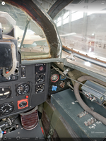
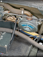
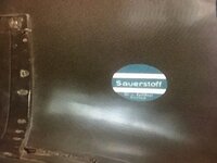
This first photo shows the port side nose and a circular inspection hatch, the second shows what is inside that circular hatch.

Me-163 Nose.JPG
Me-163 INLET Point .jpg


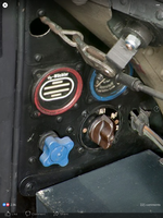
Now I read "Langsam Fullen" as 'Fill slowly' but the question is with What.

I am assuming that the Red coloured point at upper left is Compressed Air as a). there is a ball valve behind this nut and b). pipes to the Skid jacks are also painted red. Am I right ?

Also what are the other two filling points for? I had assumed the blue round the outside of the cover plate would indicate Oxygen (Saurstoffe) as all gauges and flow valves in the cockpit are also blue painted but which filler and what is the third one for? Presumably Not fuel as C=Stoff and T-stoff plates are all over the upper fuselage.

Also does anyone know what the code "Hb11" by the lower filler point mean

Anyone and ideas please?

Many thanks in advance
.
Rodd
 
Hi Wurger,

Many thanks for the excellent diagram.

I see there is not one but two systems 1). compressed air system and 2). compressed oil system or are they both Hydraulic?
Initially I thought one was a Master or Primary system ('Ha' maybe) and the other ('Hb') a secondary or reserve system in case of failure of the primary but then looking at the diagram they do not have duplicate locations so I guess that 'Ha' and 'Hb' have different functions.

Would you have a diagram or any idea of where the Oxygen filler is located please. The tanks, 3 cylindrical spheres in a row (as in Fw-190 etc.) are located under the radio mast behind the pilots headrest but I have yet to identify a filling location for them.

Thank you again for this diagram and any other help you can give.

Rodd
 
Crimea River,

Thank you for the idea.

It would be a logical place for it as the oxygen tanks are in the spine of the fuselage behind the pilots headrest and can usually be seen through the inspection window. within the rear view glazing. Also as all the cockpit gauges and control knobs are blue it would the colour to go for which is why I (wrongly) thought the blue & red stripes around the port side nose hatch were an indicator of the fill point.

I will check the wing root more carefully when I am back in the next museum week, ours has been painted a few times so it may just have disappeared into the layers of matt green paint.

Thanks again for replying

Rodd
 
Snautzer01,

Many thanks for the diagram and short filling instructions, Brilliant will be very useful.


Crimea River,

I have had a look at other Museums 163's and they have that decal (ours does not but its on its 3rd repaint) and its a warning label about Oxygen. I guess its there on the Starboard side as the Controls and gauges for the pilot are on the RH sub-panel in he cockpit so likely the pipe runs beneath this wing root panel. I will check it out next week

Cheers both

Rodd
 
Crimea River,

Here is the best close up I can manage of the Oxygen decal on a US Museum exhibit..

"Sauerstoff"
then "O? ? ???.test"
then "Halten"

is about all I can see....

Cheers

Rodd
 

Attachments

  • Me 163  SauerStoff Decal .jpg
    Me 163 SauerStoff Decal .jpg
    161.9 KB · Views: 68
Take a look at the attached cut away drawing from the Sept 1972 issue of Air Enthusiast.

No oxygen system is shown, not even the circular oxygen regulator you see on both US and German aircraft (note, we copied ours from theirs). Now, think. It had a very short flight time and utilized a spring loaded ejection seat. The pilot had to wear a special suit from protection from the rocket propellants. My conclusion is that the pilot carried his own oxygen bottle and regulator, which acted as a Bail Out Bottle as well as helping him being protected from the highly hazardous propellants.

Note that no oxygen system is shown in the cut way drawing of the Natter as well. Same reason.
 

Attachments

  • Me-163_0001.jpg
    Me-163_0001.jpg
    2 MB · Views: 56
  • Me-163_0002.jpg
    Me-163_0002.jpg
    2 MB · Views: 54
Wurger,

Many thanks for teh clarification of the wording on the decal.

Rodd
 
MIflyer

Thanks for the exploded view diagrams.

I think these may be for a 163a or something as our 163b (and others in museums in the US etc) has an Oxygen system.
See the attached photos and cut away diagram No. 14.

I just need to find out how they were filled, nothing obvious found during this weeks safety check so now wondering if its accesibble when the ammunition belt cover are removed, will have to investigate next week.

Now the "Natter" that's a whole different thing, think I'd want to be armour plated to fly that one ;)

Regards

Rodd
 

Attachments

  • IMG_1146.PNG
    IMG_1146.PNG
    1.4 MB · Views: 96
  • IMG_1147.PNG
    IMG_1147.PNG
    1.3 MB · Views: 84
  • IMG_1148.PNG
    IMG_1148.PNG
    996.4 KB · Views: 93
  • Me-163 Cut away with O2 bottles. JPG.png
    Me-163 Cut away with O2 bottles. JPG.png
    210.2 KB · Views: 106
Snautzer01,

Thank you for the Cockpit layout diagram I had been looking for a good of those. Excellent.

Thanks also for photo of the O2 regulator, as you can see from mine we still have a length of rubber tubing coming out of the top of ours, I guess the liot had some sort of plug in connection from his face mask to this pipe.

Regards

Rodd
 

Users who are viewing this thread

Back