P-51D "Creamer's Dream"

Ad: This forum contains affiliate links to products on Amazon and eBay. More information in Terms and rules

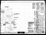
Finally - here is the Top P-51D Fuselage Installation drawing in which the 109-25001 rolls up to. It shows the P-51D-5 as the original view of the 'no DFF' production run. Around the base of the vert fin is drawn a View A, referenced below, to insert the 109-25001 DFF Assembly by name and Effectivity note [3]. Look closely at the Fin and note that it seems straight for about 1/2 of its leading edge, in contrast to the line shown on the 109-25001-1 part.

Effectivity Note [3.] found in Zone 1 of 106-31001 for the fuselage assembly of fins, doors, fillets, etc, reads as follows:

[3.] USED ON SHIPS NA109 (1001 SUBS)AAF 44-14253 SUBS AND NAA 111 (401 SUBS) AAF 44-11153 SUBS

There are no other DFF Assembly drawings for the P-51D, only for the P-51H. There is no other next Assembly for the 25001-1 Fin Assy other than the 106-31001 Installation Fuselage cover.

You may correctly assume that all swayback, slightly curved, nearly straight and straight 109-25001-3 Fins are what NAA intended to put on the P-51D series after 44-14252.
 

Attachments

  • P-51D DFF top assy - Fuse 106-25001 pg 1 jpg.JPG
    P-51D DFF top assy - Fuse 106-25001 pg 1 jpg.JPG
    3.1 MB · Views: 110
Last edited:
never mind I missed the last post entirely. I figured the DFF mod used for the B/C and the D would be a different mod isn't the fuse a little taller in the B/C than the D because on the early ac it sloped from the rear of the canopy top back to the tail section and D had the ridgeback removed. seems to me the DF for the B/C should be shorter, not as high, different angle.
 
Last edited:
For those of you who haven't seen a copy, I'll try to attach a pdf of the Statistical Digest of WWII. It is something like 18Mb, so I'm not sure if it will load. If not, I tried ...

I hasten to point out ... these are USAAF data and do not include the Navy and Marine Corps.

For that, you need another pdf, also attached.

You will note the USAAF and US Navy specifically do not save the same information. The USAAF and Navy have never exactly cooperated with one another.

It isn't all that difficult to find the USAAF aerial victory data, but the individual Navy and marine Corps aerial victory data are not easy to find. You would think the data would be simple and easy to get, wouldn't you?
 

Attachments

  • Statistical_Digest_of_WWII.pdf
    17.7 MB · Views: 65
  • Naval_Aviation_Combat_Stats_WW2.pdf
    2.6 MB · Views: 83
Last edited:
never mind I missed the last post entirely. I figured the DFF mod used for the B/C and the D would be a different mod isn't the fuse a little taller in the B/C than the D because on the early ac it sloped from the rear of the canopy top back to the tail section and D had the ridgeback removed. seems to me the DF for the B/C should be shorter, not as high, different angle.

Just the opposite case re: length of DFF. The B/C mod and C-10 production DFF attach to the fuselage at FS 237.5, while the D attaches at 248 - almost 11 inches shorter than the B/C DFF
 
The top and bottom surface of the wing from leading edge to about the 35-40% chord point was sprayed and puttied with filler, sanded and painted. The NMF aircraft were sprayed silver on the wings.
 
Many thanks.
Besides the two refilling point, that I think will not be covered with putty, on the left wing towards the tip, there is an oval access panel, in your opinion will that be covered as well?
Many thanks
Alberto
 
For those of you who haven't seen a copy, I'll try to attach a pdf of the Statistical Digest of WWII. It is something like 18Mb, so I'm not sure if it will load. If not, I tried ...

I hasten to point out ... these are USAAF data and do not include the Navy and Marine Corps.

For that, you need another pdf, also attached.


You will note the USAAF and US Navy specifically do not save the same information. The USAAF and Navy have never exactly cooperated with one another.

It isn't all that difficult to find the USAAF aerial victory data, but the individual Navy and marine Corps aerial victory data are not easy to find. You would think the data would be simple and easy to get, wouldn't you?

Thanks Greg, they worked okay for me.


Geo
 
Many thanks for your advice.
In the mean time I did an experiment on the spare tail piece: I brushed some Mr Surfacer 500 and, once dry, I sanded with wet paper 500 grit followed by 6000 grit, the output seems good.

DSCN1755.jpg
DSCN1756.jpg


Tomorrow I will try to spray on some paint and see the result.
Alberto
 
Remember, only the leading 40% of the wing was filled and sealed and painted over (except for fabric rudder which was also painted (silver for NMF, OD otherwise)
 
Remember, only the leading 40% of the wing was filled and sealed and painted over (except for fabric rudder which was also painted (silver for NMF, OD otherwise)

Many thanks.
I found this information on a book

P-51D American Aces pag 45.jpg


and this one on the web:

p51szpachla.jpg


Both of them seems to show a lot more than 40% but I'm inclined to follow your indication, so where should I stop my putting?
Many thanks
Alberto
 
At the 40% chord line. They were flush rivets all the way in that area, and even though the 'laminar flow airfoil never achieved the hopeful 40%, that area from about the forward spar all the way aft from there was immersed in separated boundary layer. For that region under a separated BL, there is no benefit of reducing either profile or friction drag by filling, sealing and spraying.
 
Great, that means an easier job for me! In facts I just did a test, airbrushing some black paint on my test piece, see above, and I found that only some panel line were filled: that mens to me that at least two layers of putty are required.
Alberto
 

Users who are viewing this thread

Back