P-51D maneuvrability - what it was in reality ...

Ad: This forum contains affiliate links to products on Amazon and eBay. More information in Terms and rules

There was never (at least known) a Mustang with a chin radiator.
You are correct.
From the P-509 onward, the Mustang never had a radiator mounted in the cowl area.

For those who wish (or need, aparently) to learn more:

 
I'm not an expert, but one, I do know what I'm talking about, and two, when I do have questions or curiosities, I ask, and I do know that a lot of people here know a lot more than I do.

There was never (at least known) a Mustang with a chin radiator. Going back to the P-509 (which evolved into the NA-73X), all Mustang developments had a ventral radiator. The closest was the Rolls-Royce Mustang X Merlin engine test beds that were converted from RAF Mustang Is. The "chin" intake housed the intercooler and supercharger intake.

The Spitfire IXe and XIVe had 2 .50 Browning MGs and 2 20mm Hispano cannons. Spitfires from the Mk V onwards that were fitted with the "C" universal wing (of which the "E" was a variant of) could house 4 20mm cannons (not standardized until the Spitfire 21).

And the Hispano cannon was much larger than the .50 MG. The numbers I've seen for the .50 Browning aircraft model ranged between 52-65 lbs, the Hispano Mk II/M2 was 100-110 lbs, the Mk V/M3/M24 was 83-88 lbs. Numbers probably vary due to presence of extra equipment vs the basic weapon. Not to mention that it was quite a bit longer.

Also, until the XP-51F/G and P-51H, the Spitfire could easily outclimb the Mustang (better power to weight ratio due to being built to lower max load standards, which means lower weight), and should've been more maneuverable (especially at lower speeds) due to lower wing loading (again related to weight, though the P-51 could easily out roll the Spitfire unless the Spitfire had clipped wings until the Mk 21).

With the XP-51F/G (which weighed roughly the same as a Spitfire IX, though it carried more than twice the fuel), you had a plane with similar wing loading to the Spitfire and combined with improved control surfaces should've been more agile than a P-51D even with the D "flying light". The P-51H (production evolution of the F/G models) was comparable in weight to the Griffon Spitfires, with a similar power to weight ratio and wing loading. Of course, no comparative flights with the F/G/H was never done against the Spitfire.

Also, for extra credit, those aforementioned planes (as well as the XP-82/P-82B at least, and maybe the Allison powered P-82E/F/G/H and XP-51J) did have a radiator design that produced a positive thrust to drag ratio (so it actually produced more thrust than drag).

Otherwise, all I can say (not being an insane expert), is, paging drgondog...
please read what i have written and not what you think i have written before posting a reply.


first up chin radiator North americans original drawings as shown to the british air ministry. there was another 4 months of redesign before an agreement was reached and constructions started. so you are correct there never was a chin mounted radiator on a P51. but then i never wrote there was one now did I?

spitfire wings, now what did i actually write? you have just confirmed what i wrote so your point is ? what?

and what was the weight of an early 1930s .50 browning unmodified by the USAF?

handling again what are you replying to? and in special regards to the P51. how much fuel was onboard. because fully loaded it was a very dangerous dog!

ap82 is post war!
 
Hey Clean32,

re weights of the 20mm HS404 and .50 cal Browning in UK & US service

The RAF Mk I & Mk II 20mm and USAAF M2 & AN/M2 20mm weighed ~51 kg(~112 lbs) with firing solenoid/trigger. The RAF recoil operated feed assist mechanism used for the belt-fed installation added another ~8.5 kg(~19 lbs), while the USAAF mechanism weighed ~6 kg(13 lbs). The late-war RAF Mk V and USAAF AN/M3 guns weighed ~38 kg(~84 lbs) bare - the RAF recoil operated feed assist for the Mk V weighed either 6.3 kg or 6.8 kg(14 lbs or 15 lbs) depending on the model used, while the USAAF recoil operated feed assist for the M3 weighed ~7 kg(15.5 lbs).

Various bits and pieces for the 20mm added from 10 lbs to 15 lbs depending on the installation. There was also a servo belt feed mechanism (used in pace of the recoil operated feed assist) on aircraft like the P-38, Beaufighter, and Mosquito. The weight of the servo feed mechanism was ~16 kg(~36 lbs).

So as a base figure for the 20mm (with belt feed) the weight was over 59 kg(130) lbs for the Mk I & Mk II and M2 & AN/M2 20mm, and over 44 kg(97 lbs) for the Mk V & AN/M3 20mm.


The US M2 & AN/M2 .50 cal Aircraft Gun (air-cooled 36" barrel) as used in WWII weighed ~29 kg(~64 lbs) with solenoid/trigger.


All the above information is from the appropriate WWII ordnance manuals.


PS maybe I missed something upthread, but what does the weight of the early-1930s .50 cal Browning have to do with WWII?
 
Last edited:
B24, was a true laminar flow wing.
laminar flow as designated by the aviation industry.

because the P51 wing was a near identical profile top and bottom. and the spitfire profile was a more traditional profile with a larger length top of the wing than the bottom of the wing.

the spitfire wing would produce lift with minim angle of attack, where the p51 wing could only produce lift with a lot of angle of attack.

so the slower the P51 is the more angle of attack it needs to crate lift, more angle of attack = more drag = more power = more fuel. until its traveling fast enough to need no angle of attack, at this point it has its minimum drag

the spitfire wing which produces more lift needed much less angle of attack as speed increased less and less angle of attack was needed. until it needed 0 deg. the most less drag at this point. BUT the down side is if speed increase past this point the wing is producing more lift than is needed. then you need a negative angle of attack. stick forward, nose down. to maintain level flight. and this increases' drag.

if you played with Kites when you were a kid. your string was attached further back in light winds and forwards in higher winds, same thing.
That seems to discuss one subject to the exclusion of all others. The difference between the P-51 wasnt purely the drag cause by the wings. The lift required for a Spitfire was not a constant, it doubled in weight from the start to the end of its career. The lift produced and required varied with the weight, altitude, speed and other stuff. As far as I have read the P-51 had less drag at all speeds up to the transonic region. At some speeds altitudes and weights etc that advantage may have been less than at others, due to the reasons you have given. Did the Spitfire fly in cruise with a negative AoA for the whole wing, it had 1.5% wing wash? Did that make the line of thrust also negative?
 
Last edited:
uumm Laminar flow wing is when the top surface and bottom surface are near identical. thus when compressibility occurs it happens at the same time and at the same distance from the leading edge. as a result there is no compressibility torque imposed on the wing.
a Laminar flow wing produces lift only by managing the angle of attack.
the P51 middle and out wing profiles are not the same top and bottom, and the chord is too far back to be a true laminar flow profile.
BUT having said that, the Chord or thickest part of the wing being so far back and being where compressibility occured, was the same profile to and bottom. thus did not produce torque on the wing. add to that the supper. brilliant tail didn't enter compressibility and was not effected by the turbulence by the wing. thus control was maintained for longer.

"Ummmm" ... no.

For laminar flow to work, two things must happen. First, the wing has to be smooth. Any rivet, gap, antenna, or other minor protrusion will make the airflow turbulent. Second, the wing has a slightly different shape. The camber, or curvature, occurs farther aft, and the leading edge is slightly narrower. At low angles of attack, that keeps the airflow orderly as it shoots across the material.


Also, a reminder, courtesy matters.
 
Last edited:
please read what i have written and not what you think i have written before posting a reply.


first up chin radiator North americans original drawings as shown to the british air ministry. there was another 4 months of redesign before an agreement was reached and constructions started. so you are correct there never was a chin mounted radiator on a P51. but then i never wrote there was one now did I?

spitfire wings, now what did i actually write? you have just confirmed what i wrote so your point is ? what?

and what was the weight of an early 1930s .50 browning unmodified by the USAF?

handling again what are you replying to? and in special regards to the P51. how much fuel was onboard. because fully loaded it was a very dangerous dog!

ap82 is post war!
Congrats - you managed to score zero on your last several posts. That achievement places you in rare company.

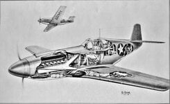
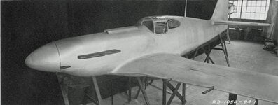
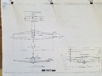
Below is the P-509 artist sketch, the mockup completed on April 16/17 1940 and the engineering three view attached to the Report NA 1592 Specification High Speed Pursuit (Allison) dated March 11 1940. To be clear both the radiator and oil cooler matrix are behind the pilot and imbedded in the fuselage.

Approximately December 1939, the P-509 General Arrangement was completed, in which the layout of the engine, cockpit, fuel tanks, radio,armament, cooling system, major airframe component, etc. volumes and weights were calculated to locate a CG, about which the wing and empennage were sized to estimate performance. The P-509 as shown and presented in March and mid April morphed considerably as the RAF/BAM/RAE and NAA engineers discussed mission and mission requirements. The P-509 grew approximately 10%+ to result in NA-73X and continued to be tweaked following release from Preliminary Design engineering or about Agust 1st as more wind tunnel data was received frm GALCIT.


Laminar Flow, strictly speaking is flow in the Reynolds Number range of ~ 500,000 to 600,000, above which flow transitions to Turbulent Flow. For your understanding , the Mustang was in Laminar Flow while taxiing toward the transient ramp. Ditto Spitfire.
 

Attachments

  • 49.1 P-509.jpg
    49.1 P-509.jpg
    2.6 MB · Views: 25
  • 58 BI412496 SC-1050-94-1 RD1050 NA-50B.jpg
    58 BI412496 SC-1050-94-1 RD1050 NA-50B.jpg
    2.1 MB · Views: 24
  • P-509-1 w Allison 3-10-40 AC 133 pg2.jpg
    P-509-1 w Allison 3-10-40 AC 133 pg2.jpg
    133.3 KB · Views: 23
"Introduction:
The results of three-component measurements and pressure and pressure distribution measurements on the airfoil of the North-American "Mustang", which were carried out in the 5 x 7 m.... wind tunnel of the DVL wind tunnel. Furthermore, the results of some tests to determine the boundary layer transition point are given....

...The Mustang-Profile is one of the best of the profiles examined in the DVL*.... the profile showed a reduced minimum drag value of 26% due to long laminar runs on both sides**, averaging 64% of the chord...as a result of the steady and relatively slow transition between the separation point and the dependence on drag, the curve here is gently rounded, and is without sudden deviations....The mustang profile has a surprising consistency in the length of the neutral point, at 24.4% of the chord, in this respect the Mustang profile gives results which differ significantly and advantageously compared to other laminar profiles so far investigated by the DVL***...The construction of the Mustang wing is aerodynamically very good and surpasses the usual German wing construction. This means that the laminar effect can also be expected to occur on the original wing."

Deutsche Luftfahrtforschung, Forschungsbericht Nr 1712, "Versuche am Tragflügelprofil des North-American Mustang", Doetsch, Berlin Adlershof, den 8.1.43.

* German Research Institute for Aviation

** This test was carried out on a real captured Mustang wing

*** "Schnitt 1,2,3" are three cuts, 1 is about mid span, and 3 is about 1 meter from the fuselage. "Tropfen Schnitt 1" is another NACA profile shown to help illustrate the profile modifications made to the Mustang wing which (the report says) did not fit into any of the known profile systems they were aware of, despite it being printed somewhere else that it was similar to a "Davis profile" (they said this was not wholly correct)

1693688986783.png
 
Last edited:
The Germans sure were lucky that they received a perfectly prepared specimen Mustang - not one that had seen service and had been shot down.

How to read the group of five numbers:
Depth of camber, percent
Distance of maximum camber from leading edge, percent
Thickness ratio, percent
Nose radius, percent
Backward position of maximum thickness from nose, percent
From NACA TM 1240
 
correct

correct, i did say built but was the original North american design.

correct

i have a 51B 65 imp gallons and 220 knots and spitfire lX at 55 imp Gallons at 200 Knts. as i said hard to get data at 8000 feet

you are comparing Griffon powered spits. apples with Lemons.

correct, and out dive
Hi Clean32,

I said Spitfire IX and XVI. Both were and are Merlin-powered. The IX was basically a Mk V airframe with a 2-stage Merlin and a 4-blade prop in place of the single-stage and 3-blade prop of the Mk V. The Spitfire XVI was the last major Merlin-powered variant before they basically switched to the Griffon for good.

You may be thinking of the Griffon-powered Spitfire XIV, but every Spitfire XVI had a Merlin.
I think a lot of them had the Packard version and went to Russia.
 
that he did.
intrestinthough, north american did not uses a Nacc profile. neither did super marine. to the best of my knowledge the only two who didn't.
Only the original series Mustang (X73 thru P-51D/K) used the proprietary NAA/NACA 45-100 airfoil. All other WWII vintage (including T-6, B-25, FJ-1 and F-86) used NACA series. The XP-51F/G/J/H and P-82 all used NACA 66 series airfoil.

To this day I still haven't found reference to the P-51 tip airfoil, but it definitely was Not 45-100
 
first up chin radiator North americans original drawings as shown to the british air ministry. there was another 4 months of redesign before an agreement was reached and constructions started. so you are correct there never was a chin mounted radiator on a P51. but then i never wrote there was one now did I?

Actually NAA did present the P-500 in January/early February 1940. It was the Ranger powered in-line pursuit intended for possible export alternative to NA-53, but the Brits quickly discarded as neither equal to current euro fighers already in production. The P-509 General Assembly work was work in progress by Schmued and one or two other engineers in Preliminary Design (Algier was one of them and the draftsman for the P-509-3).

P-509 was the basis for the original mock up, specifications and performance estimates delivered on or about March 20th, that spawned the intense review and changes that led to the mock up delivered April 17. In fact, the P-509 was not 'redesigned' until further refinements of the NA-73 mission were made several weeks AFTER the LOI was signed on April 11, 1940. The most important changes were made regarding growth of wing and fuselage due to the increase in internal fuel and final armament selection.
I did see a banner at Osprey's Facebook page of the P-51B book that showed something with a chin intake--but with items that protruded from the bottom of the cowling that looked like exhaust pipes. I thought it was some type of trainer originally.
 
I know that the P-51B (and later) Mustangs had a chin intake for the supercharger on the Merlin. That's not what I'm talking about. I don't know if you can see the picture (at all, let alone well) there's a sketch of the air-cooled plane referenced above:

 
Not sure if this is the place for this, but here is a video of ultra laminar flow proving the flow is definitely not random.


View: https://youtu.be/57IMufyoCnQ

Thought it might be interesting ... wonder what the Reynolds number range is? 0 - 1000?

So I looked into this Reynolds Number malarkey. There is nothing more infuriating than a man born in 1842 making mathematical equations I dont understand to explain things we see everyday.
 

Users who are viewing this thread

Back