I don't think too many people will be watching this video because it is "cool".
View: https://www.youtube.com/watch?v=zv83yBebiIU&t=18s
The title alone would put most people off this one, unless they took quite a distinct interest in the subject matter, like I do.
Great to express iterest in Aero and Performance - but Greg isn't the answer to a maiden's prayer. He wandered off the reservation by not truly understanding the difference between Thrust required vs Power required. Nor does he fully grasp Parasite Drag equations.
First and most important - he skipped an explanation for reducing the aero and performance equations as functions of (W, Density, Wing Area, Velocity^2). To get to his final conclusions, he needed a sound baseline of those values and the relationships to match Thrust = Drag when for given Weights and Speeds and Velocities and altitudes.
Next he fumbled though a comparison of the Thrust HP for vs Thrust for a jet engine, and in so doing completely presented his lack of knowledge regarding the basic equations - namely the explanation for the divisor value of "325" in the Thp (V)/325. The REASON is to translate KTs to Feet/Sec. The conversion factor for MPH = 375.
Units of FPS, Pounds, Slugs must be consistent to translate Thrust=Drag, Weight=Lift, Q= 1/2*rho*V^2 in pounds/SF, S=Wing area in SF, V in feet per second.
Absent those two Major discussions he missed the explanation regarding the Difference between (CL/CD)min for PropellerTHP vs (CL/CD)min for Jet Thrust.
For Power Required of jet engine, the relationship is Pr=T*V and for most is a straight line as f(T,V) from zeo to max thrust. For Recip engine Pr=n*HP*V/k where n=prop efficiency, HP = Max Hp at given altitude is non-linear and has no place in P-80 vs Me 262 comparisons.
The difference for L/Dmax at minimum power vs Thrust is:
Minimum Thrust required = CL/CD where CDo=CDi
Minimum Power required = CDo=1/3 CDi
Even the above lose precision when V> 0.3M
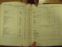
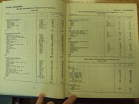
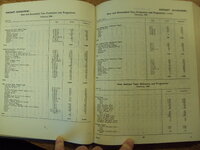
He gets into deep weeds when he simply departs from the Wight Field test reports of 1945.
What he needs is a.) GW at take-off a well as altitudes; b) Wing Areas, c.) Calculated AR = Wing Area/MCR^2, d.) CL= f( W/(1/2*rho*Area*V^2) with all units in feet per/sec for V. Wing area and Span are available for both P80 and Me 262; Thrust stated for each in the report; Comparable velocites are stated in the report. Density tables are available easily.
At Vmax for each altitude and W, F=D, F=T, Drag = CDt*(1/2*rho*Area*V^2); CDt=CDo(Mc) + CL^2/(pi*AR*e). W=Lift=CL*(1/2*rho*Area*V^2) (
DO THIS FIRST)
Absent wind tunnel data - assume both Oswald efficiencies 'e' are the same and assume Mc are the same but I feel that the P-80 with imbedded engines had less correction applied at V=0.8M. This lack (of CDm/CD vs M) kills reasonably accurate drill down to CDt, however.
Don't know if Greg knows that and it isn't clear in the Aero for Naval Aviators when they discuss CDtotal. It is a Major variable when comparing Parasite Drag totals for speeds increasing from M=0.3.
That said if you ignore all the assumptions which he makes, you can proceed as follows:
Start with Thrust = Drag; Lift =W for steady level flight. T=CDt*(1/2*rho*Wing Area*V^2). L=CDL=(1/2*rho*Area*V^2). IGNORING Mc will enable you to derive
At top speed 521mph = 521/1.467 = 355fps; for max thrust 3600 pounds at 5000 feet where from tables rho =0.8617 in lbs sec^2/Ft^4; Lift = 10,200 pounds.
From there CL is straightforward. CL^2/piAR is straight forward.
From T=D and L=W
T=D= 1/2rho*Area*V^2*CD; W=L=1/2rho*Area*V^2*CL
T/W=CD/CL------> T=W(CL/CD) = W/(L/D) =
Calculate CDi based on CL at max V.
CL=W/(1/2*rho*Area*V^2) where rho = density.
Assume e=1. CDi= CL^2/(pi*AR)
for P-80, CDt80 + CL^2/(Pi*AR)80; same for Me 262 but with different values extracted as function of Wing Area/MAC^2 for different AR, different gross weights, different total thrust.
When both are calculated as described, The CL80 and CL 262, combined with Thrustp80 and Thrustme262 give you the following equations which will be populated by using different speeds to fill out the curve based on CDp and CLi*2
CDt-CL^2 = 3600 - CL^2 = CDp for that altitude. To fill in a chart of CD vs CL, you then perform the repeated calculations for changing velocity due to lower power as Cdp remains the same for the same altitude.
NOTE - you may Not assume CDo remains the same for different Reynold's number as RN = f(rho*V*MAC/Mu) where Rho/Mu (density over absolute viscosity) leads to V*MACx10^5/Kinematic Viscosity) - in other words changes somewhat linearly with increasing altitude.
For sound performance analysis the relationship CD at given altitude and velocity is derived from wind tunnel and expressed as CDp2 = CDp1(RN1/RN2)^y.
For wind tunnel derived data CDp for a model is recorded for different airframe components at RN (say 100mph) and then varied until an expression for a particular airframe is derived. (For a P-51B the CDp1 = 0.019 at RN1=1.84x10^6 and the empiical formula = CDp2 = (RN11/RN2)^0.11. the range of RN are then calculated as above RN2=V*MAC/kinematic Viscosity.
Additionally, Greg overlooked a major CDp variable which increases with altitude - namely the variation of CL vs CDcl. At Lift Coefficient <0.2it is neglibible but increases non- linearly as altitude density decreases. If you look above, with L=W constant, the CL varies inversely proportional to density - which makes CL increase 2X from SL to 26000 feet.
Therefore the Parasite Drag equations are
CDp = (CDp1+Delta CDp1 + Delta CDp2)* Mc where CDp1 is the Minimum Parasite Drag Component often expressed as CDo (CDp of wing, fuselage, empenage, ducts, cockpit, exhaust stacks for RN1)
Delta CDp1 include gun ports, antenna, leaks, friction) also a function of RN1
Delta CDp2 is the increment due to change in angle of attack, given as a plot of CD vs CL (lift co-efficent) ---- NOT Induced Drag
Mc is the ratio of CD at a specific Mach number versus CD for wind tunnel derived CD at low velocity/low altitude/Low RN. Non linear. For Mustang the CDm doubles from 0.3M to 0.4M and doubles again from 0.4M to 0.5M and doubles again from 0.5M to 0.6M and gain from 0.6M to 0.7M
The final drag equations are CDp = (CDp1+Delta CDp1+Delta CDp2)*Mc + CL^2/pi*AR*e
L/D is at Max when dTr/dV=0 for Jet Thrust required; On T vs V plot this is at the bottom of the combined CDo=CDi where the Drag equation is CDt=(CDp)*Mc+ CDi. All of Gregs pontifications ignore Mach corrections to CDt above ~ 0.3M. All his calculations miss the difference between reciprocating engine Power versus jet engine power equations and basic principles of non-linear Power required as function of velocity for recip, versus basic straight line slope of jet engine as function of velocity.
This is a Major issue when trying to find CDo at low speed when deriving CDo at high speed corrected for Mach, number as 'built in' to CDt = CDp + CDi . The CDp decrease in a major way as Speed decreases from M=0.8 to M=0.3 or whatever the P-80 CDp reduces to when nearing the low point of CDt plot.
There is a LOT more but gets down to tacky nits.
Here are the only accurate conclusions you can draw from Gerg's foray into Aerodynamics for Naval Aviators;
1. Me 262 was a better performer that P-80
2. The P-80, with far less thrust to play with was close to Me 262 so one may conclude that it was aerodynamically cleaner. Probably but in reality I know they were close. in drag
3. If cruise data was presented - that would yield quickly the CL, the approximate CDmin and therefore the CL/CDmax for Glide slope calcs.
4. Stick to lectures on subjects that don't require sound understanding of Aero and Flight Mechanics based on Aero