"The case for the P-47 Thunderbolt being the greatest fighter of the Second World War " (1 Viewer)

Ad: This forum contains affiliate links to products on Amazon and eBay. More information in Terms and rules

Just so that YOU are aware, I have posted a screen shot of my copy of the book "Republic's P47 Thunderbolt From Seversky to Victory" by Warren Bodie.

I decided to get it out of a less accessible part of the house where it sat with all of the other aviation material I own.

As it says "Seversky" in the title, I am sure you will now accept that I knew that there was a change in the company structure/name in 1939.

Or do you need more convincing?

I am sure that most reasonable people will be happy enough with me just using the "Republic" moniker at any point in these discussions.

View attachment 715273
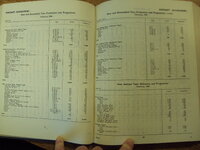
If it makes you feel good, by all means, go for it.

The point being: when one is giving grief to others for minutiae, be sure to be accurate in statements.
 
Can we all go home now ?

1681283160964.png
 
Apart from 44-64181/KL987 sent to Britain as part of the exchange program the USAAF retained all P-51H, similar for P-47N. China was officially allocated 50 P-51C under Lend-Lease, delivered in August 1944, but did not receive all of them. Later transfers include P-51D, I have only gone through the serials near the allocated block 44-11043 to 92 so the attached is a sample. Note some of the transfer dates. Similarly post war some P-47D ended up in Chinese service, but that,
like the exact numbers of P-51, requires going through the USAAF aircraft cards.

The wing racks came with the P-47D-15-RE (42-76119 accepted on 30 November 1943) and D-15-RA (42-23143 also 30 November 1943). As noted then allow 1 to 2 months before the types arrived in Britain, similar for any US made drop tanks. Early December 1943 a P-47D in the US could be fitted with 3 large drop tanks, not so in Britain except for any local conversions.

For details on RAF operations in support of the USAAF bombers look at the Fighter Command War Diaries, the RAF apparently came to the conclusion earlier the bombers were the best way of attracting Luftwaffe fighters versus sweeps. The Mighty Eighth War Diary notes escorts were used as early as 13 March 1943, when they failed to meet up with the bombers. P-47 escorts to 175 miles out on the 4 May 1943 raid on Antwerp.

USAAF Delivery Logs extract, British drop tank production, unfortunately the reports begin in December 1943.
 

Attachments

  • China P-51.pdf
    2.3 MB · Views: 43
  • Picture 001.jpg
    Picture 001.jpg
    513.1 KB · Views: 47
  • Picture 019.jpg
    Picture 019.jpg
    493.7 KB · Views: 45
  • Picture 076.jpg
    Picture 076.jpg
    511.5 KB · Views: 44
Last edited:
Apart from 44-64181/KL987 sent to Britain as part of the exchange program the USAAF retained all P-51H, similar for P-47N. China was officially allocated 50 P-51C under Lend-Lease, delivered in August 1944, but did not receive all of them. Later transfers include P-51D, I have only gone through the serials near the allocated block 44-11043 to 92 so the attached is a sample. Note some of the transfer dates. Similarly post war some P-47D ended up in Chinese service, but that,
like the exact numbers of P-51, requires going through the USAAF aircraft cards.

The wing racks came with the P-47D-15-RE (42-76119 accepted on 30 November 1943) and D-15-RA (42-23143 also 30 November 1943). As noted then allow 1 to 2 months before the types arrived in Britain, similar for any US made drop tanks. Early December 1943 a P-47D in the US could be fitted with 3 large drop tanks, not so in Britain except for any local conversions.

For details on RAF operations in support of the USAAF bombers look at the Fighter Command War Diaries, the RAF apparently came to the conclusion earlier the bombers were the best way of attracting Luftwaffe fighters versus sweeps. The Mighty Eighth War Diary notes escorts were used as early as 13 March 1943, when they failed to meet up with the bombers. P-47 escorts to 175 miles out on the 4 May 1943 raid on Antwerp.

USAAF Delivery Logs extract, British drop tank production, unfortunately the reports begin in December 1943.
The RAF started using bombers as bait in Jan 1941 with the aptly named Circus Operations. As it turned out Clown Show may have been even more appropriate.
 
I don't think too many people will be watching this video because it is "cool".


View: https://www.youtube.com/watch?v=zv83yBebiIU&t=18s

The title alone would put most people off this one, unless they took quite a distinct interest in the subject matter, like I do.

Great to express iterest in Aero and Performance - but Greg isn't the answer to a maiden's prayer. He wandered off the reservation by not truly understanding the difference between Thrust required vs Power required. Nor does he fully grasp Parasite Drag equations.

First and most important - he skipped an explanation for reducing the aero and performance equations as functions of (W, Density, Wing Area, Velocity^2). To get to his final conclusions, he needed a sound baseline of those values and the relationships to match Thrust = Drag when for given Weights and Speeds and Velocities and altitudes.

Next he fumbled though a comparison of the Thrust HP for vs Thrust for a jet engine, and in so doing completely presented his lack of knowledge regarding the basic equations - namely the explanation for the divisor value of "325" in the Thp (V)/325. The REASON is to translate KTs to Feet/Sec. The conversion factor for MPH = 375.

Units of FPS, Pounds, Slugs must be consistent to translate Thrust=Drag, Weight=Lift, Q= 1/2*rho*V^2 in pounds/SF, S=Wing area in SF, V in feet per second.

Absent those two Major discussions he missed the explanation regarding the Difference between (CL/CD)min for PropellerTHP vs (CL/CD)min for Jet Thrust.
For Power Required of jet engine, the relationship is Pr=T*V and for most is a straight line as f(T,V) from zeo to max thrust. For Recip engine Pr=n*HP*V/k where n=prop efficiency, HP = Max Hp at given altitude is non-linear and has no place in P-80 vs Me 262 comparisons.

The difference for L/Dmax at minimum power vs Thrust is:
Minimum Thrust required = CL/CD where CDo=CDi
Minimum Power required = CDo=1/3 CDi
Even the above lose precision when V> 0.3M

He gets into deep weeds when he simply departs from the Wight Field test reports of 1945.
What he needs is a.) GW at take-off a well as altitudes; b) Wing Areas, c.) Calculated AR = Wing Area/MCR^2, d.) CL= f( W/(1/2*rho*Area*V^2) with all units in feet per/sec for V. Wing area and Span are available for both P80 and Me 262; Thrust stated for each in the report; Comparable velocites are stated in the report. Density tables are available easily.

At Vmax for each altitude and W, F=D, F=T, Drag = CDt*(1/2*rho*Area*V^2); CDt=CDo(Mc) + CL^2/(pi*AR*e). W=Lift=CL*(1/2*rho*Area*V^2) (DO THIS FIRST)

Absent wind tunnel data - assume both Oswald efficiencies 'e' are the same and assume Mc are the same but I feel that the P-80 with imbedded engines had less correction applied at V=0.8M. This lack (of CDm/CD vs M) kills reasonably accurate drill down to CDt, however.
Don't know if Greg knows that and it isn't clear in the Aero for Naval Aviators when they discuss CDtotal. It is a Major variable when comparing Parasite Drag totals for speeds increasing from M=0.3.

That said if you ignore all the assumptions which he makes, you can proceed as follows:

Start with Thrust = Drag; Lift =W for steady level flight. T=CDt*(1/2*rho*Wing Area*V^2). L=CDL=(1/2*rho*Area*V^2). IGNORING Mc will enable you to derive
At top speed 521mph = 521/1.467 = 355fps; for max thrust 3600 pounds at 5000 feet where from tables rho =0.8617 in lbs sec^2/Ft^4; Lift = 10,200 pounds.
From there CL is straightforward. CL^2/piAR is straight forward.
From T=D and L=W
T=D= 1/2rho*Area*V^2*CD; W=L=1/2rho*Area*V^2*CL

T/W=CD/CL------> T=W(CL/CD) = W/(L/D) =

Calculate CDi based on CL at max V.
CL=W/(1/2*rho*Area*V^2) where rho = density.
Assume e=1. CDi= CL^2/(pi*AR)

for P-80, CDt80 + CL^2/(Pi*AR)80; same for Me 262 but with different values extracted as function of Wing Area/MAC^2 for different AR, different gross weights, different total thrust.

When both are calculated as described, The CL80 and CL 262, combined with Thrustp80 and Thrustme262 give you the following equations which will be populated by using different speeds to fill out the curve based on CDp and CLi*2
CDt-CL^2 = 3600 - CL^2 = CDp for that altitude. To fill in a chart of CD vs CL, you then perform the repeated calculations for changing velocity due to lower power as Cdp remains the same for the same altitude.

NOTE - you may Not assume CDo remains the same for different Reynold's number as RN = f(rho*V*MAC/Mu) where Rho/Mu (density over absolute viscosity) leads to V*MACx10^5/Kinematic Viscosity) - in other words changes somewhat linearly with increasing altitude.

For sound performance analysis the relationship CD at given altitude and velocity is derived from wind tunnel and expressed as CDp2 = CDp1(RN1/RN2)^y.

For wind tunnel derived data CDp for a model is recorded for different airframe components at RN (say 100mph) and then varied until an expression for a particular airframe is derived. (For a P-51B the CDp1 = 0.019 at RN1=1.84x10^6 and the empiical formula = CDp2 = (RN11/RN2)^0.11. the range of RN are then calculated as above RN2=V*MAC/kinematic Viscosity.

Additionally, Greg overlooked a major CDp variable which increases with altitude - namely the variation of CL vs CDcl. At Lift Coefficient <0.2it is neglibible but increases non- linearly as altitude density decreases. If you look above, with L=W constant, the CL varies inversely proportional to density - which makes CL increase 2X from SL to 26000 feet.

Therefore the Parasite Drag equations are
CDp = (CDp1+Delta CDp1 + Delta CDp2)* Mc where CDp1 is the Minimum Parasite Drag Component often expressed as CDo (CDp of wing, fuselage, empenage, ducts, cockpit, exhaust stacks for RN1)
Delta CDp1 include gun ports, antenna, leaks, friction) also a function of RN1
Delta CDp2 is the increment due to change in angle of attack, given as a plot of CD vs CL (lift co-efficent) ---- NOT Induced Drag
Mc is the ratio of CD at a specific Mach number versus CD for wind tunnel derived CD at low velocity/low altitude/Low RN. Non linear. For Mustang the CDm doubles from 0.3M to 0.4M and doubles again from 0.4M to 0.5M and doubles again from 0.5M to 0.6M and gain from 0.6M to 0.7M

The final drag equations are CDp = (CDp1+Delta CDp1+Delta CDp2)*Mc + CL^2/pi*AR*e

L/D is at Max when dTr/dV=0 for Jet Thrust required; On T vs V plot this is at the bottom of the combined CDo=CDi where the Drag equation is CDt=(CDp)*Mc+ CDi. All of Gregs pontifications ignore Mach corrections to CDt above ~ 0.3M. All his calculations miss the difference between reciprocating engine Power versus jet engine power equations and basic principles of non-linear Power required as function of velocity for recip, versus basic straight line slope of jet engine as function of velocity.

This is a Major issue when trying to find CDo at low speed when deriving CDo at high speed corrected for Mach, number as 'built in' to CDt = CDp + CDi . The CDp decrease in a major way as Speed decreases from M=0.8 to M=0.3 or whatever the P-80 CDp reduces to when nearing the low point of CDt plot.

There is a LOT more but gets down to tacky nits.

Here are the only accurate conclusions you can draw from Gerg's foray into Aerodynamics for Naval Aviators;
1. Me 262 was a better performer that P-80
2. The P-80, with far less thrust to play with was close to Me 262 so one may conclude that it was aerodynamically cleaner. Probably but in reality I know they were close. in drag
3. If cruise data was presented - that would yield quickly the CL, the approximate CDmin and therefore the CL/CDmax for Glide slope calcs.
4. Stick to lectures on subjects that don't require sound understanding of Aero and Flight Mechanics based on Aero
 
I have no idea if the USAAC had a certain range in mind for their fighters. I have not seen anything that says that one way or another.

The P-38, P-39 and P-40 were all designed with much larger fuel tanks and suffered a cut in range with self sealing tanks were installed. They got drop tanks apparently to restore the range ?
The P-47 was designed with self sealing tanks and is supposed to have been able to fly over 800 miles at low speed at low altitude which much further than the P-39 and P-40 could fly without drop tanks once they had self sealing tanks. It was also about twice as far as most European fighters could fly under the same conditions. It was not enough to escort bombers Flying across the English channel and the occupied countries
One of the reasons to design for ferry tanks was the daunting distances contemplated for Pacific operations. Certainly restoring some lost tankage due to self sealing tank replacements was a factor.
Somehow, I just knew that was going to happen, while I am still digesting the "second order curves" you dropped in the other day.
To better understand 'second order curves' think of successive conical cross sections with strict attention to continuous smooth transition from prop to cockpit area. Schmued was a bear regarding installing bumps, intakes, antenna, etc in the areas most critical for smooth flowing air and incremental increasing pressure gradients. As stark examples, look at P-40 or Typhoon or Bf 109D/E 'up front design' compared to Mustang I. Or original FW 190 design to P-47
 
To better understand 'second order curves' think of successive conical cross sections with strict attention to continuous smooth transition from prop to cockpit area. Schmued was a bear regarding installing bumps, intakes, antenna, etc in the areas most critical for smooth flowing air and incremental increasing pressure gradients. As stark examples, look at P-40 or Typhoon or Bf 109D/E 'up front design' compared to Mustang I. Or original FW 190 design to P-47
Thanks drgondog, its something that you sort of notice without realising that it can be expressed mathematically or that placing draggy items aft of the centre of lift was significant, I knew it was in certain cases but thought that was for specific reasons like a Hurricane tail wheel.
 
The P47, as I have pointed out to you many times, could not accept tanks until late 1942 BECAUSE IT DID NOT HAVE THE PLUMBING FOR IT.
This is my issue with the whole discussion, you state that the P-47 "could not accept tanks until late 1942 BECAUSE IT DID NOT HAVE THE PLUMBING FOR IT." As if that is some game changing argument. It could not accept them before late 1942 because it wasnt there, they only started to arrive in September. Late 1942 is 9 or 10 months after Hap Arnolds "decree" was rescinded. It was 4 to 5 months before the P-47 started operations from UK. 9 months before the first Schweinfurt raid and 15 months before Operation Argument. It does not matter precisely how long because we are talking about an age in WW2 terms. It also doesnt matter how many were not plumbed whether it is 100 or 1000, there was a war on. NAA started installing fuselage tanks and shipped kits to install in planes already made, job done. At the start of 1940 the British replaced the wings on every Hurricane in service and changed the props, installed rear armour and BP glass on all Spitfires and Hurricanes, job done. The P-47 required unlimited time to achieve the simplest tasks and some evil empire takes the blame. As pointed out by S/R every other US fighter had drop tanks at the time. The whole "bomber mafia" theory needs you to suspend all logic and reference to a calendar to believe it.
 
Last edited:
Dimlee -- If this post is not an April Fools joke and is really what AI gave you, it is both fascinating and horrifying! I can't help thinking about how much potential misinformation and disinformation could be spread by this thing. Combine your AI experience with Wikipedia and what do you have?
No jokes. Chat GPT can be extremely useful or a waste of time and a complete disappointment...
 
The RAF started using bombers as bait in Jan 1941 with the aptly named Circus Operations. As it turned out Clown Show may have been even more appropriate.
There is little doubt the RAF hit peak inefficiency around 1941, the loss of pre war regulars coupled with the need for numbers meant production of existing types and cuts to training. The RAF generally had less well trained aircrew operating aircraft with lower performance compared with the Luftwaffe. Many lessons were still making their way up the chain of command, the Butt report is the classic example. People seeing what they expected to see meant throughout the Battle of Britain the RAF kept reporting vics of Bf109, so in 1941 the RAF fighters were still using close vic formation. The German radar could pick the bomber formations from their slower speeds, leading to fighter speeds being cut, not great for turning sightings into favourable fights.

There were few targets in France the Germans needed to defend, even fewer of these within RAF fighter range, and the RAF could have a viable day or a viable night bomber force, not both in 1941/42, so the weight of attack was low. Essentially the Luftwaffe day fighter force in the west could be kept small, well trained with the latest equipment and was usually able pick its fights, as the chances of the RAF doing anything really destructive were small. Leading to stories of Luftwaffe fighters doing aerobatics displays to lure RAF fighters away from the main formation rather than a straight interception. "Johnny" Johnson talking about luring the Luftwaffe fighters into engagements. The day air fighting in the west 1941 and 1942 was a major tactical victory for the Luftwaffe, and a strategic defeat, they were unable to prevent the growth of the enemy air force, in quality and quantity. The RAF needed to maintain a large home fighter force, sending it over France to gain combat experience part of keeping it ready, but the fighter commanders made plenty of mistakes, like largely accepting current fighter range limits, compounding their weak tactical situation.

In late 1942 and increasingly in 1943 the USAAF supplied the lure, a viable, growing day bomber force, the Luftwaffe fighters had more pressure to engage to stop its effectiveness and growth and not just over Germany.

As bomb groups took around 12 months to form and become trained the 8th Air Force in 1943 was the product of decisions taken in 1941, including the ratio of fighters to bombers. Given the technology of 1941/42 if the USAAF was to bomb Germany by day the bombers had to largely take care of themselves by at least preventing many killing fighter attacks or perhaps saturate the defences enough overall losses enable the campaign to continue. By then the RAF did not believe in the self defending bomber so was happy to escort raids on French targets, plus insertion and withdrawal cover for more distant raids. It had a large underemployed fighter force.

The self defending idea did not apply the medium and light bombers, they were expected to have escorts and the RAF generally provided them in 1943, while Bomber Command dropped around 1,230 long tons of bombs by day in the first half of 1943, the USAAF light and medium bombers managed 8,203 short tons mostly in the second half of 1943. As the tempo of allied operations went up the Luftwaffe was being pushed into more unfavourable tactical situations. The Spitfire V was in trouble in 1942 as it was the main target of the higher performance Bf109G and Fw190A, it did better in 1943, partly as Germans could not tell the difference between it and a IX until too late but also because it ceased being the main target, a role taken over by the bombers.
 
Great to express iterest in Aero and Performance - but Greg isn't the answer to a maiden's prayer. He wandered off the reservation by not truly understanding the difference between Thrust required vs Power required. Nor does he fully grasp Parasite Drag equations.

First and most important - he skipped an explanation for reducing the aero and performance equations as functions of (W, Density, Wing Area, Velocity^2). To get to his final conclusions, he needed a sound baseline of those values and the relationships to match Thrust = Drag when for given Weights and Speeds and Velocities and altitudes.

Next he fumbled though a comparison of the Thrust HP for vs Thrust for a jet engine, and in so doing completely presented his lack of knowledge regarding the basic equations - namely the explanation for the divisor value of "325" in the Thp (V)/325. The REASON is to translate KTs to Feet/Sec. The conversion factor for MPH = 375.

Units of FPS, Pounds, Slugs must be consistent to translate Thrust=Drag, Weight=Lift, Q= 1/2*rho*V^2 in pounds/SF, S=Wing area in SF, V in feet per second.

Absent those two Major discussions he missed the explanation regarding the Difference between (CL/CD)min for PropellerTHP vs (CL/CD)min for Jet Thrust.
For Power Required of jet engine, the relationship is Pr=T*V and for most is a straight line as f(T,V) from zeo to max thrust. For Recip engine Pr=n*HP*V/k where n=prop efficiency, HP = Max Hp at given altitude is non-linear and has no place in P-80 vs Me 262 comparisons.

The difference for L/Dmax at minimum power vs Thrust is:
Minimum Thrust required = CL/CD where CDo=CDi
Minimum Power required = CDo=1/3 CDi
Even the above lose precision when V> 0.3M

He gets into deep weeds when he simply departs from the Wight Field test reports of 1945.
What he needs is a.) GW at take-off a well as altitudes; b) Wing Areas, c.) Calculated AR = Wing Area/MCR^2, d.) CL= f( W/(1/2*rho*Area*V^2) with all units in feet per/sec for V. Wing area and Span are available for both P80 and Me 262; Thrust stated for each in the report; Comparable velocites are stated in the report. Density tables are available easily.

At Vmax for each altitude and W, F=D, F=T, Drag = CDt*(1/2*rho*Area*V^2); CDt=CDo(Mc) + CL^2/(pi*AR*e). W=Lift=CL*(1/2*rho*Area*V^2) (DO THIS FIRST)

Absent wind tunnel data - assume both Oswald efficiencies 'e' are the same and assume Mc are the same but I feel that the P-80 with imbedded engines had less correction applied at V=0.8M. This lack (of CDm/CD vs M) kills reasonably accurate drill down to CDt, however.
Don't know if Greg knows that and it isn't clear in the Aero for Naval Aviators when they discuss CDtotal. It is a Major variable when comparing Parasite Drag totals for speeds increasing from M=0.3.

That said if you ignore all the assumptions which he makes, you can proceed as follows:

Start with Thrust = Drag; Lift =W for steady level flight. T=CDt*(1/2*rho*Wing Area*V^2). L=CDL=(1/2*rho*Area*V^2). IGNORING Mc will enable you to derive
At top speed 521mph = 521/1.467 = 355fps; for max thrust 3600 pounds at 5000 feet where from tables rho =0.8617 in lbs sec^2/Ft^4; Lift = 10,200 pounds.
From there CL is straightforward. CL^2/piAR is straight forward.
From T=D and L=W
T=D= 1/2rho*Area*V^2*CD; W=L=1/2rho*Area*V^2*CL

T/W=CD/CL------> T=W(CL/CD) = W/(L/D) =

Calculate CDi based on CL at max V.
CL=W/(1/2*rho*Area*V^2) where rho = density.
Assume e=1. CDi= CL^2/(pi*AR)

for P-80, CDt80 + CL^2/(Pi*AR)80; same for Me 262 but with different values extracted as function of Wing Area/MAC^2 for different AR, different gross weights, different total thrust.

When both are calculated as described, The CL80 and CL 262, combined with Thrustp80 and Thrustme262 give you the following equations which will be populated by using different speeds to fill out the curve based on CDp and CLi*2
CDt-CL^2 = 3600 - CL^2 = CDp for that altitude. To fill in a chart of CD vs CL, you then perform the repeated calculations for changing velocity due to lower power as Cdp remains the same for the same altitude.

NOTE - you may Not assume CDo remains the same for different Reynold's number as RN = f(rho*V*MAC/Mu) where Rho/Mu (density over absolute viscosity) leads to V*MACx10^5/Kinematic Viscosity) - in other words changes somewhat linearly with increasing altitude.

For sound performance analysis the relationship CD at given altitude and velocity is derived from wind tunnel and expressed as CDp2 = CDp1(RN1/RN2)^y.

For wind tunnel derived data CDp for a model is recorded for different airframe components at RN (say 100mph) and then varied until an expression for a particular airframe is derived. (For a P-51B the CDp1 = 0.019 at RN1=1.84x10^6 and the empiical formula = CDp2 = (RN11/RN2)^0.11. the range of RN are then calculated as above RN2=V*MAC/kinematic Viscosity.

Additionally, Greg overlooked a major CDp variable which increases with altitude - namely the variation of CL vs CDcl. At Lift Coefficient <0.2it is neglibible but increases non- linearly as altitude density decreases. If you look above, with L=W constant, the CL varies inversely proportional to density - which makes CL increase 2X from SL to 26000 feet.

Therefore the Parasite Drag equations are
CDp = (CDp1+Delta CDp1 + Delta CDp2)* Mc where CDp1 is the Minimum Parasite Drag Component often expressed as CDo (CDp of wing, fuselage, empenage, ducts, cockpit, exhaust stacks for RN1)
Delta CDp1 include gun ports, antenna, leaks, friction) also a function of RN1
Delta CDp2 is the increment due to change in angle of attack, given as a plot of CD vs CL (lift co-efficent) ---- NOT Induced Drag
Mc is the ratio of CD at a specific Mach number versus CD for wind tunnel derived CD at low velocity/low altitude/Low RN. Non linear. For Mustang the CDm doubles from 0.3M to 0.4M and doubles again from 0.4M to 0.5M and doubles again from 0.5M to 0.6M and gain from 0.6M to 0.7M

The final drag equations are CDp = (CDp1+Delta CDp1+Delta CDp2)*Mc + CL^2/pi*AR*e

L/D is at Max when dTr/dV=0 for Jet Thrust required; On T vs V plot this is at the bottom of the combined CDo=CDi where the Drag equation is CDt=(CDp)*Mc+ CDi. All of Gregs pontifications ignore Mach corrections to CDt above ~ 0.3M. All his calculations miss the difference between reciprocating engine Power versus jet engine power equations and basic principles of non-linear Power required as function of velocity for recip, versus basic straight line slope of jet engine as function of velocity.

This is a Major issue when trying to find CDo at low speed when deriving CDo at high speed corrected for Mach, number as 'built in' to CDt = CDp + CDi . The CDp decrease in a major way as Speed decreases from M=0.8 to M=0.3 or whatever the P-80 CDp reduces to when nearing the low point of CDt plot.

There is a LOT more but gets down to tacky nits.

Here are the only accurate conclusions you can draw from Gerg's foray into Aerodynamics for Naval Aviators;
1. Me 262 was a better performer that P-80
2. The P-80, with far less thrust to play with was close to Me 262 so one may conclude that it was aerodynamically cleaner. Probably but in reality I know they were close. in drag
3. If cruise data was presented - that would yield quickly the CL, the approximate CDmin and therefore the CL/CDmax for Glide slope calcs.
4. Stick to lectures on subjects that don't require sound understanding of Aero and Flight Mechanics based on Aero
Yeah... what he said...

I totally grok this in its fullness. o_O
 
And how can you prove that you do?

You might but I have no way of knowing but likewise you have no ability to look down on those just because they like to watch his videos.
I really don't think you understand how this all works.

Just because someone has XXX viewers of his videos does not make him an expert. Because he talks with authority and sounds like he knows the material inside and out does not mean he does.

Some terms you might familiarize yourself with before throwing shade on some of the denizens here:

Peer Review
Source Documents
Actual Aero Related Studies/Degrees
Industry Related Experience and/or Military Experience Related to a Specific Field
Source Documents
Peer Review

I put those last two in again because the people you are arguing with, specifically D Deleted member 68059 and drgondog drgondog (Just to name two (2)) are experts in their respective disciplines. Why are they considered experts (and not just by us here)? See above.

You're not conversing with armchair experts here, these fellows have done the research of digging out facts to support whatever statement they choose to give. They have done the actual (hard) work it takes to make true written statements that can stand any light shone on them and still stand up as true.

That this Greg is a pilot is nice, so are many here, I was too at one time, that does NOT make me an expert on everything aero related. Far from it and I can point to an actual spot on the ground as my bona fides that attest to that fact.

Pardon the verbose response, I have a tendency to chunter on and it's a bad habit of mine. Apologies.

But dude you're arguing with the wrong people on the wrong subject in the wrong place at the wrong time.
 
That this Greg is a pilot is nice, so are many here, I was too at one time, that does NOT make me an expert on everything aero related. Far from it and I can point to an actual spot on the ground as my bona fides that attest to that fact.

Uh, speak for yourself. I'm a Piper Cherokee pilot, that makes me an expert P-47 and P-51 Ace. In fact I could tangle with BiffF15 BiffF15 in an Eagle. In fact I might head down to the ramp, get in one, put a Twisted Sister tape in the cassette deck and show Doug Masters how its done.

:D

I'll show myself the door now.
When you could buy a civil licensed P-51 for $5000, some people with your experience bought one and checked themselves out. Some of them survived although the airplane usually didn't.
 

Users who are viewing this thread

Back