The N1K2-J Shiden Kai vs Its US Counterpart (2 Viewers)

My understanding is that the Hellcat's split flaps' degree of deflection is automatically controlled by the compression spring. It should work like this:

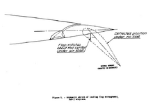
As speed increases, lift pressure increases, progressively compressing the spring. As the spring compresses, the slotted flap gradually moves from 50 degrees to 0 degrees. The degree of incidence and design would provide a lot of lift (although higher drag in the stowed/retracted position).

The Shiden's automatic flap system appears to both progressively extend and change angle of incidence based on airspeed. It should be more effective and incur less drag at low speed compared to the slotted-flaps on the Hellcat. On paper the flap moves to 30-degrees of incidence, but then it has a neat trick where it can pop a split flap (which causes a lot of drag, too). Shiden pilots mentioned that they used it for interception missions where they'd activate it at the top of an immelmann to reduce turn radius and stall speed.


Kawanishi used a wing-fuselage fillet of four degrees in order to improve wing root stall characteristics while the flaps were deployed. Because the flaps are located at the wing root and when flying at low speeds, and the airfoil was experimental, this led to stall issues with the N1K1-J. It was known to autorotate easily during flight, probably because with flaps lowered, stalls began at the wingtip rather than at the wing root. This seems to explain why the Shiden-Kai has a larger fillet than the Shiden. I think this is because the automatic flap system had enormous lift and it probably made it a significantly better dogfighter than the Hellcat. But the tradeoff was additional drag.
My understanding is that the Hellcat's split flaps' degree of deflection is automatically controlled by the compression spring. It should work like this:

As speed increases, lift pressure increases, progressively compressing the spring. As the spring compresses, the slotted flap gradually moves from 50 degrees to 0 degrees. The degree of incidence and design would provide a lot of lift (although higher drag in the stowed/retracted position).

The Shiden's automatic flap system appears to both progressively extend and change angle of incidence based on airspeed. It should be more effective and incur less drag at low speed compared to the slotted-flaps on the Hellcat. On paper the flap moves to 30-degrees of incidence, but then it has a neat trick where it can pop a split flap (which causes a lot of drag, too). Shiden pilots mentioned that they used it for interception missions where they'd activate it at the top of an immelmann to reduce turn radius and stall speed.


Kawanishi used a wing-fuselage fillet of four degrees in order to improve wing root stall characteristics while the flaps were deployed. Because the flaps are located at the wing root and when flying at low speeds, and the airfoil was experimental, this led to stall issues with the N1K1-J. It was known to autorotate easily during flight, probably because with flaps lowered, stalls began at the wingtip rather than at the wing root. This seems to explain why the Shiden-Kai has a larger fillet than the Shiden. I think this is because the automatic flap system had enormous lift and it probably made it a significantly better dogfighter than the Hellcat. But the tradeoff was additional drag.
871CBF81-1288-4EB2-B464-A8A841D68163.jpeg
832A32DD-5F7F-4383-ABF6-ACD566A107FD.jpeg


Actual gun cam footage on N1K2's combat flap:
C7C7FFDC-13F6-474C-8451-12914CF9EF82.gif

This actual scene above the Bungo strait in July 1945. The shooter was Lt. Malcom Cagle, the leader of VF-88 piloting an F6F-5. He just wounded the famous Muto Kaneyoshi's N1K2 in the head-on pass, and came in to help this F4U. Who was caught in a turn by this N1K2 using flaps, and Cagle came in to shoot it down reporting "No difficulty in following despite enemy used flaps while F6F didn't plus a belly tank".

In the same battle, Oshibuchi's N1K2 was outmaneuvered and shot down by an F6F using flaps, a fight between N1K's flap and F6F's flap.
3DB93217-6CB2-4AC2-B980-46390028160C.jpeg
 
My theory is that Grumman's "automatic" flap's major goal is to increase the lateral stability of the aircraft during deck landing, instead of maneuvering.
What you say totally lines up with the available information, thank you for clearing up that point of contention. Some of this comment goes over my head, but what I do understand makes sense.
However the flaps on Shiden is very small when compared with the one on the Hellcat, and considering laminar airfoil was used on it, thus it generates much less overall lift coefficient. A good guess is 1.8-1.9 with flaps fully dropped( power off). The Japanese essay gives N1K's power on CLmax in turning 1.9 clean and 2.5 when automatic flap operated in 19deg.
I think the Shiden-Kai manual has information on the flap area when extended but my copy is unreadable. In the video you provided, they look huge compared to the Hellcat's flaps, although the hellcat's flaps appear to be almost twice as long as the Shiden's.

Regardless, it's great knowing that the Hellcat's flaps were used successfully in combat... and that they were highly useful!

This actual scene above the Bungo strait in July 1945. The shooter was Lt. Malcom Cagle, the leader of VF-88 piloting an F6F-5. He just wounded the famous Muto Kaneyoshi's N1K2 in the head-on pass, and came in to help this F4U. Who was caught in a turn by this N1K2 using flaps, and Cagle came in to shoot it down reporting "No difficulty in following despite enemy used flaps while F6F didn't plus a belly tank".

In the same battle, Oshibuchi's N1K2 was outmaneuvered and shot down by an F6F using flaps, a fight between N1K's flap and F6F's flap.
Wow, thank you for sharing this video footage.

The description of this dogfight in "Genda's Blade" explains why the George got shot down. The pilot, Nobuya Komeda, didn't see Cagle until it was too late. Komeda was engaged in a turning fight with a Naval pilot by the name of Applegate, which Applegate was unable to escape from. The description indicates that Cagle had altitude advantage and surprise. Komeda didn't have a lot of energy to work with when Caggle opened up on him. The video ends too early. Apparently the Shiden's tail gets shot off.

Oshibushi, on the other hand, was flying an already damaged aircraft, although the author of Genda's Blade did not mention what the nature of the damage was. According to the pilot chasing him, Oshibushi tried to enter a flat turn several times, but stopped after being fired at. When the Hellcat got within the firing converge range, it connected on a Shiden that was flying straight and level.

Most, if not all, of the dogfights in the book indicate that the George could out-turn the Hellcat at certain speeds. My guess is that the Hellcat probably had a superior instantaneous turn but its sustained turn was likely inferior. The Shiden probably had significantly lower drag based on wing area, the flap type, frontal area, and airfoil data. So my guess is that the Hellcat was better at split-s maneuvers and the George II was better at energy tactics (spiral climbs).
 
I think the Shiden-Kai manual has information on the flap area when extended but my copy is unreadable. In the video you provided, they look huge compared to the Hellcat's flaps, although the hellcat's flaps appear to be almost twice as long as the Shiden's.
There used to be a very in depth post on the old War Thunder forum about the Shidens automatic flaps, but sadly the old forum has been deleted. There was a lot of really good research on there...
 
What you say totally lines up with the available information, thank you for clearing up that point of contention. Some of this comment goes over my head, but what I do understand makes sense.

I think the Shiden-Kai manual has information on the flap area when extended but my copy is unreadable. In the video you provided, they look huge compared to the Hellcat's flaps, although the hellcat's flaps appear to be almost twice as long as the Shiden's.

Regardless, it's great knowing that the Hellcat's flaps were used successfully in combat... and that they were highly useful!


Wow, thank you for sharing this video footage.

The description of this dogfight in "Genda's Blade" explains why the George got shot down. The pilot, Nobuya Komeda, didn't see Cagle until it was too late. Komeda was engaged in a turning fight with a Naval pilot by the name of Applegate, which Applegate was unable to escape from. The description indicates that Cagle had altitude advantage and surprise. Komeda didn't have a lot of energy to work with when Caggle opened up on him. The video ends too early. Apparently the Shiden's tail gets shot
Wild take-off and pull-out of an F6F-5K, demonstrating the enormous flap lift of the Hellcat. Note the plane is still carrying a drop tank.


The plane under remote control experienced stall roll-off several times, but remained controllable. Which is what "lateral stability" comes in to play.

Comparing a Corsair stalls in wave-off condition( flap gear down, power on). You would see the difference.
 
View attachment 874258View attachment 874259

Actual gun cam footage on N1K2's combat flap:
View attachment 874263
This actual scene above the Bungo strait in July 1945. The shooter was Lt. Malcom Cagle, the leader of VF-88 piloting an F6F-5. He just wounded the famous Muto Kaneyoshi's N1K2 in the head-on pass, and came in to help this F4U. Who was caught in a turn by this N1K2 using flaps, and Cagle came in to shoot it down reporting "No difficulty in following despite enemy used flaps while F6F didn't plus a belly tank".

In the same battle, Oshibuchi's N1K2 was outmaneuvered and shot down by an F6F using flaps, a fight between N1K's flap and F6F's flap.
View attachment 874264

Both planes had their landing gear down during the dogfight... I can't believe it
 
Both planes had their landing gear down during the dogfight... I can't believe it
According to "Genda's Blade", after Oshibushi's Shiden-Kai got blasted by Cagle's guns, the landing gear dropped. To not overshoot, Cagle had to drop his flaps and landing gear.

I suspect that Oshibushi's undercarriage had already partially dropped due to the Shiden Kai's known issue with the landing gear even before the fighting began due to other pilots mentioning his plane was damaged.

It's similar to when Thomas McGuire crashed and his wingman got shot down. He was flying with his drop tanks equipped and the Frank pilot also had his drop tank, or bomb, on due to malfunction.
 
My understanding is that the Hellcat's split flaps' degree of deflection is automatically controlled by the compression spring. It should work like this:

As speed increases, lift pressure increases, progressively compressing the spring. As the spring compresses, the slotted flap gradually moves from 50 degrees to 0 degrees. The degree of incidence and design would provide a lot of lift (although higher drag in the stowed/retracted position).

The Shiden's automatic flap system appears to both progressively extend and change angle of incidence based on airspeed. It should be more effective and incur less drag at low speed compared to the slotted-flaps on the Hellcat. On paper the flap moves to 30-degrees of incidence, but then it has a neat trick where it can pop a split flap (which causes a lot of drag, too). Shiden pilots mentioned that they used it for interception missions where they'd activate it at the top of an immelmann to reduce turn radius and stall speed.


Kawanishi used a wing-fuselage fillet of four degrees in order to improve wing root stall characteristics while the flaps were deployed. Because the flaps are located at the wing root and when flying at low speeds, and the airfoil was experimental, this led to stall issues with the N1K1-J. It was known to autorotate easily during flight, probably because with flaps lowered, stalls began at the wingtip rather than at the wing root. This seems to explain why the Shiden-Kai has a larger fillet than the Shiden. I think this is because the automatic flap system had enormous lift and it probably made it a significantly better dogfighter than the Hellcat. But the tradeoff was additional drag.
A very interesting point is that, N1K1-J has an unusually large wing-fuselage fillet for a midwing design, almost comparable or larger than most low-wing aircrafts. Normally, one would expect aircrafts that use mid-wing to have no or very small wing fillet, example such as F6F & F4U had no wing fillet, while F4F and P-47 had very small wing fillet, due to the nature of mid-wing produces the smallest wing-fuselage intereference. As N1K2-J switched to low-wing, one would expect it to have even larger fillet, which we have seen it is almost made the Shiden-Kai a wing-fuselage blended design.

It could be that the unusually large incidence angle of the Shiden's wing root (4deg), in combination with an unusually large wing twist (-3.5deg) that negatively impacted the aircraft's wing root vortex and lift. Most WW2 monoplane fighter tend to not use wing twist larger than -2.5deg, as it negatively the aircraft's maximum lift coefficient and zero-lift drag coefficient, even though offering a better stall characteristc and potentially better induced drag property. In comparison, the Hellcat has a wing incidence of 3deg and a twist of 0deg, so does the Corsair with 2 deg incidence and 0deg twist, both obtained good L/D efficiency at low speed and better lift property.

Even with large incidence and large wing twist, the Shiden has problem with interference and bad stall characteristc, which lead its aerodynamic details much to be doubtful. Even though the aircraft had a relatively good overall performance.
 
Last edited:
A very interesting point is that, N1K1-J has an unusually large wing-fuselage fillet for a midwing design, almost comparable or larger than most low-wing aircrafts. Normally, one would expect aircrafts that use mid-wing to have no or very small wing fillet, example such as F6F & F4U had no wing fillet, while F4F and P-47 had very small wing fillet, due to the nature of mid-wing produces the smallest wing-fuselage intereference. As N1K2-J switched to low-wing, one would expect it to have even larger fillet, which we have seen it is almost made the Shiden-Kai a wing-fuselage blended design.

It could be that the unusually large incidence angle of the Shiden's wing root (4deg), in combination with an unusually large wing twist (-3.5deg) that negatively impacted the aircraft's wing root vortex and lift. Most WW2 monoplane fighter tend to not use wing twist larger than -2.5deg, as it negatively the aircraft's maximum lift coefficient and zero-lift drag coefficient, even though offering a better stall characteristc and potentially better induced drag property. In comparison, the Hellcat has a wing incidence of 3deg and a twist of 0deg, so does the Corsair with 2 deg incidence and 0deg twist, both obtained good L/D efficiency at low speed and better lift property.

Even with large incidence and large wing twist, the Shiden has problem with interference and bad stall characteristc, which lead its aerodynamic details much to be doubtful. Even though the aircraft had a relatively good overall performance.
Thanks for your comment, very interesting and much appreciated. So, are you suggesting that the midwing configuration should have led to smaller fillets because of lower interference drag? The Kyofu (Rex) had similarly large fillets, which seemingly contradicts my original hypothesis that the big wing root fillets would have been for improving handling on short runways, particularly when climbing. Seaplanes have unlimited runway. High angle of attack would experience more lift, less parasitic drag from wing-root vortices, etc.. The original Kyofu design was an attempt to squeeze as much aerodynamic juice out of a plane as possible. Kawanishi went with counter-rotating props, laminar foil, and midwing-mounted wings. My best guess now is that it must have been for aerodynamics

But Japanese Wikipedia mentions that the A1 Skyraider had a similar 4-degree twist but without a large fillet. As a carrier attack aircraft, it was designed for loiter time and (apparently) excellent maneuverability, along with flaps that were near the wing root. So the degree of wing twist and flaps probably have nothing to do with the fillet.

As N1K2-J switched to low-wing, one would expect it to have even larger fillet, which we have seen it is almost made the Shiden-Kai a wing-fuselage blended design.

I'm still not sure why they had so much fillet to begin with, but it has something to do with the N1K1-J being prone to autorotation and flat spins, even with the flaps deployed. All the other laminar airfoil aircraft fielded by the Japanese (with the exception of possibly the Saiun/Myrt) used laminar airfoils on the inner portion of the wing and traditional airfoils on the outer portion because they distrusted the stall characteristics of laminar flow airfoils.

But because the Rex/Kyofu was designed at the outset for speed above all else, and it didn't require an airstrip, it might be that its airfoil was fully laminar. This would explain the Shiden's poor handling characteristics and what sounds like a tendency to stall at the wingtips first. The majority of N1K1-J were lost in accidents so Kawanishi probably decided to make the fillets huge to counterbalance the airfoil's low turbulence/low lift characteristics
 
Thanks for your comment, very interesting and much appreciated. So, are you suggesting that the midwing configuration should have led to smaller fillets because of lower interference drag? The Kyofu (Rex) had similarly large fillets, which seemingly contradicts my original hypothesis that the big wing root fillets would have been for improving handling on short runways, particularly when climbing. Seaplanes have unlimited runway. High angle of attack would experience more lift, less parasitic drag from wing-root vortices, etc.. The original Kyofu design was an attempt to squeeze as much aerodynamic juice out of a plane as possible. Kawanishi went with counter-rotating props, laminar foil, and midwing-mounted wings. My best guess now is that it must have been for aerodynamics

But Japanese Wikipedia mentions that the A1 Skyraider had a similar 4-degree twist but without a large fillet. As a carrier attack aircraft, it was designed for loiter time and (apparently) excellent maneuverability, along with flaps that were near the wing root. So the degree of wing twist and flaps probably have nothing to do with the fillet.


I'm still not sure why they had so much fillet to begin with, but it has something to do with the N1K1-J being prone to autorotation and flat spins, even with the flaps deployed. All the other laminar airfoil aircraft fielded by the Japanese (with the exception of possibly the Saiun/Myrt) used laminar airfoils on the inner portion of the wing and traditional airfoils on the outer portion because they distrusted the stall characteristics of laminar flow airfoils.

But because the Rex/Kyofu was designed at the outset for speed above all else, and it didn't require an airstrip, it might be that its airfoil was fully laminar. This would explain the Shiden's poor handling characteristics and what sounds like a tendency to stall at the wingtips first. The majority of N1K1-J were lost in accidents so Kawanishi probably decided to make the fillets huge to counterbalance the airfoil's low turbulence/low lift characteristics
Well for the AD or Skyraider it is quite interesting, one have to be noted is that, "twist" can be both aerodynamical and geometrical, an aerodynamical twist reffering by using airfoils of different zero-aoa lift along spans, while geometrical twist actually twist the wing downward towards the tip.

The "twist" I have just mentioned was referring to geometrical twist, since F6F and F4U uses the same series airfoil NACA230xx, only decreased thickness/chord ratio along the span, so there was no aerodynamical twist, and the wing also had 0 deg geometrical twist angle. The N1K also uses the same airfoil design along span, but twist the airfoil downwards toward the tip, which had 0 deg aerodynamical twist and -3.5 deg geometrical twist.

For the AD Skyraider, the wing consists of NACA2417 at the root and NACA4413 at the tip, i.e different airfoils with different zero lift aoa. NACA4413 starts to produce lift at say -4 deg aoa, and NACA2217 at say -2 deg (I havn't look it up), which equivalent to twist the wing 2 deg upward. As the wing has a -4 deg geometrical twist, the overal twist is (-2 -(-4)) - 4 = -2deg, which lies in a reasonable range to improve lift property (NACA44 has better CLmax than NACA24), while preserves stall characteristics at the same time (root at larger aoa and stalls first than the tip).

Note the AD was a Douglas design that used more conventional NACA 4-digits airfoil, rather than 5-digits NACA230, which may harm the trimmed CLmax of the AD a little bit due to larger downward pitching, but made the plane safer (NACA230xx has the best over CL, CD and Cm but produces bad stall).

All the other laminar airfoil aircraft fielded by the Japanese (with the exception of possibly the Saiun/Myrt) used laminar airfoils on the inner portion of the wing and traditional airfoils on the outer portion because they distrusted the stall characteristics of laminar flow airfoils.
Actually the laminar airfoil should be used at outer wing spans, as the inner wing spans are exposed to proppeller streams and they are "dirty" full of turbulances, would make laminar airfoil pointless. I heard the A7M used conventional airfoils for inner sections and laminar at outer sections, which should be correct.

The Kyofu (Rex) had similarly large fillets, which seemingly contradicts my original hypothesis that the big wing root fillets would have been for improving handling on short runways, particularly when climbing. Seaplanes have unlimited runway. High angle of attack would experience more lift, less parasitic drag from wing-root vortices, etc.. The original Kyofu design was an attempt to squeeze as much aerodynamic juice out of a plane as possible. Kawanishi went with counter-rotating props, laminar foil, and midwing-mounted wings. My best guess now is that it must have been for aerodynamics
I've heard that some aircrafts do have a tendency to "dutch-roll" when flaps were lowered, which is indeed related to wing-fuselage intereference, so the fillet of Shiden may be added to improve this property. I'm not sure why lots of other mid-wing aircraft (F6F,F4U,F8F and P-47) has no such problem, probably they had a strong lateral and directional stability to overcome this effect, while also uses blow-up flap to reduce the inner-flap angle so to mitigate this effect. Or it is possible that Shiden's flap produces more turbulence than American design, even though it looks quite similar to F6F's slotted flap design in 2D, except that it carried with a small split flap at the end.
 
Last edited:
I've heard that some aircrafts do have a tendency to "dutch-roll" when flaps were lowered, which is indeed related to wing-fuselage intereference, so the fillet of Shiden may be added to improve this property. I'm not sure why lots of other mid-wing aircraft (F6F,F4U,F8F and P-47) has no such problem, probably they had a strong lateral and directional stability to overcome this effect, while also uses blow-up flap to reduce the inner-flap angle so to mitigate this effect. Or it is possible that Shiden's flap produces more turbulence than American design, even though it looks quite similar to F6F's slotted flap design in 2D, except that it carried with a small split flap at the end.
They were not related to the aerodynamic butterfly flaps used on Nakajima aircraft. They appear to be fowler flaps with that split flap on the end. They were probably high lift with proportionate drag, depending on the flaps' angle setting.

I think you have the best explanation for why those fillets are so huge. The extra lift provided by the fillets probably counteract some undesired flight characteristic. I used a more sophisticated translator on the J-Wiki article on the Shiden Kai:

A distinctive trait inherited from its floatplane‑fighter origins

The main wing carried over from the Kyōfū floatplane fighter had an unusually large wing‑root incidence angle of 4 degrees—something almost unheard of for a fighter. For comparison, the Hien (Ki‑61) used 0 degrees, the Fw 190 used 3 degrees, and most fighters fall somewhere within that range. Seaplanes are generally designed with lower wing loading than land‑based aircraft, but because the Kyōfū was expected to achieve high speeds, its wing loading was set relatively high. To preserve adequate water‑takeoff performance under those conditions, the designers appear to have increased the incidence angle of the wing section within the propeller slipstream. (ATD69 NOTE: this explains the high AoI)

The result was that, on its maiden flight, the Kyōfū experienced wing‑root stall turbulence striking the horizontal stabilizer as soon as the flaps were retracted, causing noticeable vibration. Although it was a mid‑wing aircraft, it required enlarged wing fillets to counter the problem. The low‑wing Shiden‑kai (N1K2‑J) needed even larger fillets, which imposed aerodynamic and weight penalties. By contrast, the J6K1 Jinpu, designed from the outset as a land‑based fighter by the same Kawanishi design team, used a wing incidence angle of just 2 degrees.

The A‑1 Skyraider also used a 4‑degree wing incidence angle, but it employed an older NACA 2417 airfoil at the wing root and a square‑section lower fuselage, allowing it to avoid the need for fillets entirely. The internal width between its left and right flaps matched the fuselage width—forming a sharp contrast with the Kyōfū and Shiden (Kai), whose flap width and area were reduced because of their large fillets.
If this translation is to be trusted, then the fillet was inherited from the Kyofu/Rex because wing-root stall was causing turbulence and that was interfering with the horizontal stabilizer and causing vibration. In this case, the flaps were preventing it.

Actually the laminar airfoil should be used at outer wing spans, as the inner wing spans are exposed to proppeller streams and they are "dirty" full of turbulances, would make laminar airfoil pointless. I heard the A7M used conventional airfoils for inner sections and laminar at outer sections, which should be correct.
I'm glad that you mentioned this point. My understanding of the translated materials is that it's the reverse. Many Japanese designers preferred a gradual transition from laminar on the inner wing to a higher degree of lift on the outer wing. At least, that's how the Reppu (Sam), Raiden (Jack), and (AFAIK) Saiun (Myrt) were designed. Here's a quote from Japanese Wikipedia:
The wing-shaped is a semi-layered wing whose inner wing becomes a laminar-flow wing, and the outer wing becomes a semi-layered wing that becomes a normal wing-shaped as it goes outside. The structure is a single-digit structure that takes mass production into consideration, and follows the method of raiden , which passes RAIDEN , with the 35% position of the wing string as a straight line to the left and right.[[13]​
There's some translation issues, but I think the main point is clear. The hybrid airfoil design reduces wingtip stalls. The huge fillets however would probably generate more lift at high angles of attack, so that would tilt things back toward a wingtip stall, particularly while climbing! The flaps, similarly, would also be within the prop slipstream's energized air and would generated a lot more lift. This again should make the aircraft more likely to stall at the wingtips rather than at the root.
 
They were not related to the aerodynamic butterfly flaps used on Nakajima aircraft. They appear to be fowler flaps with that split flap on the end. They were probably high lift with proportionate drag, depending on the flaps' angle setting.
The Nakajima's butterfly flap is of classical fowler flap, which the flap was a part of lower part of flap with the trailing edge of the wing not moving. The flap on N1K and A7M are of slotted type and I just have another look on it and discovered an unusal feature --- they have two different actuating mechanisms that can make the flap to be lowered as slightly different type:

A7M's flap:

1775886431620.png

  • When the flap is in conventional mode and been lowered as a landing flap, the main flap acts as a hinged slotted flap, quite similar to F4U Corsair's flap design, provides both high drag and high lift, whcih helps to slow down the plane when landing.
  • When the flap is in combat mode and been lowered by squeezing the button on the joystick, the main flap extends and acts as a extensible slotted flap, with much larger gap between the main wing, kind similar to F6F Hellcat's flap design, that provides high lift but lower drag, and in smaller deflection angle, this setting is ideal to be used as a combat flap.

This is very interesting as the combat flap not only mean a smaller deflection angle, but a totally different actuation mode, the same on the N1K:
Conventional mode:
1775886841731.jpeg
--- as a hinged flap
Combat mode:
1775886863590.png
--- as an extensible slotted flap, and it is actually more of a fowler as the flap moves along a sliding rail.

As have been discussed in P-47D-30 automatic flaps mystery vs Chat GPT

F6F's flap may also consists of both defelection units and extensible units, but never made them into selectable modes, maunally actuate them can be implict. The Japanese on the other hand, mixed up with both mechanism and made them selectable for the pilot, and the operation is very explictly displayed.

F6F's flap:
1775887235913.png


Another point that I admire Japanese combat flap is the placement of the control button --- they put it on the joystick, instead of on the left of the cockpit that often seen on American design. Which made the operation of wing flap during a manuver very easy, the pilot don't have to move his hand, only his finger. The American flaps switch were critisized on JFC "doubt anyone could reach them in a turn fight against Jap", and even though on an F6F the pilot can put the flap switch to "down" before the combat and can wait till a moment he enters a slow turn and flaps automatically drops. He couldn't dynamically control the flap during the turn.

I personally placed flap switch on my joystick when playing WarThunder and IL-2, found it placement to be extremely useful in a dogfight.
 

Attachments

  • 1775886801860.png
    1775886801860.png
    12.8 KB · Views: 33
I'm glad that you mentioned this point. My understanding of the translated materials is that it's the reverse. Many Japanese designers preferred a gradual transition from laminar on the inner wing to a higher degree of lift on the outer wing. At least, that's how the Reppu (Sam), Raiden (Jack), and (AFAIK) Saiun (Myrt) were designed. Here's a quote from Japanese Wikipedia:

There's some translation issues, but I think the main point is clear. The hybrid airfoil design reduces wingtip stalls. The huge fillets however would probably generate more lift at high angles of attack, so that would tilt things back toward a wingtip stall, particularly while climbing! The flaps, similarly, would also be within the prop slipstream's energized air and would generated a lot more lift. This again should make the aircraft more likely to stall at the wingtips rather than at the root.
Indeed I've consulted a friend of mine who is an expert in Japanese aviation, and yes the A7M uses laminar at the inner portion and conventional at the outer portion. It can be a compromis for lift property and stalling characteristic of the aircraft, but it reduces the effect of the laminar airfoil to a minimal. The CD0 (zero-lift drag coefficient) of the A7M2 prototype as included in one of the test-flight material, shows 0.0209 which is only equivalent to the early production F6F-3's 0.0206 and it is actually more draggier than the A6M3 ( CD = 0.021 and CD0 probably around 0.019-0.020).

Just as the example of the AD Skyraider that I've included, the airfoil transit to the type with more lift towards to tip is common, and A7M might have used this practice, just as the A6M used NACA2315 at root and NACA3309 at tip, the P-39 uses NACA00xx at root and NACA230xx at tip, and the P-38 uses NACA230xx at root and NACA44xx at tip.
 
Indeed I've consulted a friend of mine who is an expert in Japanese aviation, and yes the A7M uses laminar at the inner portion and conventional at the outer portion. It can be a compromis for lift property and stalling characteristic of the aircraft, but it reduces the effect of the laminar airfoil to a minimal. The CD0 (zero-lift drag coefficient) of the A7M2 prototype as included in one of the test-flight material, shows 0.0209 which is only equivalent to the early production F6F-3's 0.0206 and it is actually more draggier than the A6M3 ( CD = 0.021 and CD0 probably around 0.019-0.020).

Thanks for providing the CD0. My understanding is that there are no official sources for the Reppu's CD0 and that the numbers that are reported online were synthetically generated using non-primary source data. But if there is a primary source out there, that would be amazing. Are you referencing the data for CD0 and CDA from this website?

Interestingly, there are no synthetic CD0 or CDA calculations for the Shiden-Kai in the source above. If you know of any, please let me know, I'm very interested. I would guess that the CD0 and CDA are lower for the N1K1-J compared to the N1K2-J due to the mid fuseage wing mounting.

But even though those values are synthetic and of dubious pedigree, they have the ring of truth to them. It's interesting that the J2M3 has a higher CD0 and a CDA compared to the N1K1-J (which has the lowest CD0 out of all Japanese aircraft, by a significant margin). And the J2M3 has a smaller wing area too. If these numbers are accurate, it means that Mitsubishi's extensive streamlining failed to achieve much at all.

The Nakajima's butterfly flap is of classical fowler flap, which the flap was a part of lower part of flap with the trailing edge of the wing not moving. The flap on N1K and A7M are of slotted type and I just have another look on it and discovered an unusal feature --- they have two different actuating mechanisms that can make the flap to be lowered as slightly different type:
There's a post here that covers some of the intracacies of the Nakajima butterfly flaps. They were fowler-like but with some differences, such as a paddled design for reducing drag, as well as rack-and-pinion actuation, which allowed for rapid deployment in flight.
 
The N1K was originally designed as a float plane, so the wing/wingroot design was most likely modified to compensate for the deletion of the drag penalty created by the central pontoon and two outriders.

I also thought it was interesting that when the N1K made the transition to a land-based fighter, it retained it's "N" designation (N - Seaplane Fighter) instead of being redesignated "J" (Land-based Fighter).
 
Thanks for providing the CD0. My understanding is that there are no official sources for the Reppu's CD0 and that the numbers that are reported online were synthetically generated using non-primary source data. But if there is a primary source out there, that would be amazing. Are you referencing the data for CD0 and CDA from this website?

Interestingly, there are no synthetic CD0 or CDA calculations for the Shiden-Kai in the source above. If you know of any, please let me know, I'm very interested. I would guess that the CD0 and CDA are lower for the N1K1-J compared to the N1K2-J due to the mid fuseage wing mounting.
1776045546059.png

The CD0 for the A7M2 came from a primary source, as included in the test flight data flown by Kofukuda Terufumi, as he was calcualting the level flight CD @ CL = 0.28 in a cruise flight for fuel consumption. CD = CD0 + CDi

The CD that I have calculated most used level flight CAS vs. engine brake horsepower at sea level, then assuming a propeller efficiency 83%, and an Oswald = 0.8 as a standard.
For example, an F6F-3's speed vs power curve as included in NAS Pax flight test mostly indicated 310mph @ 1800 BHP,
By applying formula
C_D = (2 * eta * P) / (rho * V_fps**3 * S)
A level flight CD = 0.0221
As the aircraft's weight, AR and speed known, we then calculate flying CL to get CDi, CD0 = CD - CDi to obtain CD0 = 0.0206.

To be noted, actual aircraft's CDmin may be offseted a bit from zero-lift condition, but this calculation is a common practice as you would see the same process been done by Kofukuda flying his A7M2.

For the CD of J2M and N1K so far I haven't obtain any reliable source for the corrected sea level speed vs power data. As for the Ki-84, the rough estimate for the prototype is around CD = 0.0244 which is a bit high. This may because of its engine and propeller efficency not as good, as a Japanese source included Ki-84 had a propeller efficiency of 76% and this leads to a CD=0.0231, about the same level as the P-47.

By applying this method plus a power curve, the speed curve could be obtained, note some calculations may be incompleted.
1776046893591.png
 
Last edited:
The N1K was originally designed as a float plane, so the wing/wingroot design was most likely modified to compensate for the deletion of the drag penalty created by the central pontoon and two outriders.

I also thought it was interesting that when the N1K made the transition to a land-based fighter, it retained it's "N" designation (N - Seaplane Fighter) instead of being redesignated "J" (Land-based Fighter).

On Japanese Wikipedia the Kyofu supposedly (according to a multi-pass AI translation using different LLMs) had the extra large fillet to help with wingroot stall. But once Kawanishi's test pilot took the plane up for the first flight, once flaps were retracted, there was extreme wingroot stall, which caused severe vibrations. This meant they would have had to increase fillet angle even further to increase lift at high angles of attack. I Irregualr23 pointed out that the midwing design helped with the aerodynamics and when they switched to a low-wing design, they would have had to further increase fillet angle. But AI is so unreliable, I have to question whether all of this is correct. It sounds right to me, but I can't think of anything special about Shiden's design that would have tipped it so far toward wingroot stall.


For the CD of J2M and N1K so far I haven't obtain any reliable source for the corrected sea level speed vs power data. As for the Ki-84, the rough estimate for the prototype is around CD = 0.0244 which is a bit high. This may because of its engine and propeller efficency not as good, as a Japanese source included Ki-84 had a propeller efficiency of 76% and this leads to a CD=0.0231, about the same level as the P-47.

By applying this method plus a power curve, the speed curve could be obtained, note some calculations may be incompleted.
The issue with the Pe-32 propeller is that the evidence we have is all secondary and from non-primary sources. The information I saw here and on the Secret Weapons site showed that the Pe-32's main problem was its very shallow prop governor angles. But Japanese companies had the licenses to a number of prop governor designs, both electric and hydraulic, which were vastly superior to the ratier-type used by the Pe-32. I could believe that early protoypes of the Pe-32 could have had poor pitch angles because Japanese electrical motors of the time period were notoriously bad, compared to the cutting edge stuff from elsewhere.

We're talking about a major industrial power of that era. Maybe the fourth or fifth most technically sophisticated economy on the planet in terms of industrial output and technical achievement. It's unlikely that their propellers would be that crippled and they couldn't come up with a hydraulic alternative.

I don't think prop efficiency impacts drag though. If the Ki-84's prop were total garbage, it's CD0 and CDA should not be impacted.

EDIT: Ah, i realize you were saying that the Ki-84's CD was reverse engineered from top speed. One problem is that we lack good technical information on many Japanese aircraft because much of it was destroyed at the end of the war.
 
Last edited:
On Japanese Wikipedia the Kyofu supposedly (according to a multi-pass AI translation using different LLMs) had the extra large fillet to help with wingroot stall. But once Kawanishi's test pilot took the plane up for the first flight, once flaps were retracted, there was extreme wingroot stall, which caused severe vibrations. This meant they would have had to increase fillet angle even further to increase lift at high angles of attack. I Irregualr23 pointed out that the midwing design helped with the aerodynamics and when they switched to a low-wing design, they would have had to further increase fillet angle. But AI is so unreliable, I have to question whether all of this is correct. It sounds right to me, but I can't think of anything special about Shiden's design that would have tipped it so far toward wingroot stall.
Not sure but I believe the increase in wing-root incidence was to increase the 0-aoa lift for an aircraft about its thrust line, thus the airplane would lift-off more easily without putting too much nose up, which can be important for a seaplane as its thrust line would be parallel with the ground during the initial-stage of a take-off.

Also in related models you would see the fillet been enlarged on the N1K2 as expected:
1776130551187.jpg

1776130537280.jpg


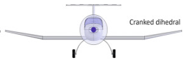
Besides the N1K, I also heard that the J2Ms were suffered from the wing-fuselage intereference and only until they used cranked-dihedral on the A7M (like how the Hellcat and Corsair did) to make sure the wing connected to the fuselage in a more perpendicular angle to eleminate this problem.

1776130588383.png


The issue with the Pe-32 propeller is that the evidence we have is all secondary and from non-primary sources. The information I saw here and on the Secret Weapons site showed that the Pe-32's main problem was its very shallow prop governor angles. But Japanese companies had the licenses to a number of prop governor designs, both electric and hydraulic, which were vastly superior to the ratier-type used by the Pe-32. I could believe that early protoypes of the Pe-32 could have had poor pitch angles because Japanese electrical motors of the time period were notoriously bad, compared to the cutting edge stuff from elsewhere.
During the TAIU tests for Ki-84 vs. Seafire, it was found the constant speed unit for Pe-32 would not function properly, and every time they tried to push Ki-84 a 600kph level flight, the propeller starts to overspeed and prevented to reach its maximum speed.

1776130781952.png


The calculation of CD has to be set with a certain propeller efficiency, which is how CD=0.0244 for 83% eta and CD=0.0231 for 76% eta. Assuming all airplanes to have the same propeller efficiency, the one who suffered from bad propeller would equivalently be more draggier.
 

Attachments

  • 1776130634093.png
    1776130634093.png
    14.7 KB · Views: 35
Last edited:
Not sure but I believe the increase in wing-root incidence was to increase the 0-aoa lift for an aircraft about its thrust line, thus the airplane would lift-off more easily without putting too much nose up, which can be important for a seaplane as its thrust line would be parallel with the ground during the initial-stage of a take-off.

Also in related models you would see the fillet been enlarged on the N1K2 as expected:
View attachment 875451
View attachment 875450

Besides the N1K, I also heard that the J2Ms were suffered from the wing-fuselage intereference and only until they used cranked-dihedral on the A7M (like how the Hellcat and Corsair did) to make sure the wing connected to the fuselage in a more perpendicular angle to eleminate this problem.

View attachment 875452


During the TAIU tests for Ki-84 vs. Seafire, it was found the constant speed unit for Pe-32 would not function properly, and every time they tried to push Ki-84 a 600kph level flight, the propeller starts to overspeed and prevented to reach its maximum speed.

View attachment 875456

The calculation of CD has to be set with a certain propeller efficiency, which is how CD=0.0244 for 83% eta and CD=0.0231 for 76% eta. Assuming all airplanes to have the same propeller efficiency, the one who suffered from bad propeller would equivalently be more draggier.
Sorry, I edited my comment yesterday afternoon after realizing you were using reversed engineered flight data to estimate CD.

Regarding the overspeed issue, there's an interesting story from a defunct website periodical: aeroplanemonthly.com. In the February 2016 issue, there's a report that sounds very similar to the story about the Hayate being tested by TAIU against a Seafire. As I cannot find the original source for the Hayate experiencing overspeed, I suspect that someone retold the story with a Frank in place of the Jack.
"Airscrew operation is
satisfactory at normal revs but hunts
at higher revs at about 10,000ft,
although it should be noted that
airscrew control on this particular
aircraft had been changed from
hydraulic to electric, so is non-
standard.


I believe (without any source) that this particular Raiden was overspeeding in dives. As the quote above shows, the electric governor was mismatched and hunting is a precursor to overspeed. I think electric props in general were less reliable compared to hydraulic pitch governors. It's been mentioned that the Japanese electric motor industry of the 1940s was not reliable (few nations could produce reliable electric motors anyway except maybe the US). They had issues with low torque and crap dampening, which meant slow and irregular pitch angle changes. This in turn caused overspeed problems. I doubt that the overspeed issue was related to the true top speed of the Ki-84. It would have been normal behavior on a pitch governor with a poorly made electric motor, which was most of them.

Regarding the fillet, you could be correct. The Wikipedia article mentioned that the vibrations occurred following the retraction of the flaps. So this implies a high angle of attack, but I'm not certain. But also, it wouldn't make sense to keep a feature from a seaplane in a land-based fighter. Why wouldn't they remove the fillet?
 

Users who are viewing this thread

Back