- Thread starter
- #21
Grant Barr
Senior Airman
Thanks all for the feedback and information -it's greatly appreciated. I've been beavering away on this kit hoping to get it progressed before I inevitably lose some motivation! Lots to put up in this post...
Having set up the cockpit I proceeded with the installation of it and the tailwheel well. Sadly both did not sit comfortably within the fuselage - this was expected having done some dry fitting when I had the fuselage and wings mocked up at the beginning. The biggest pain with the cockpit was the armoured head plate. According to the instructions the kit part was to be glued directly above the panel behind the seat. In theory this looked great but the problem was it resulted in the head plate being nearly 2mm too high to fit into the fuselage. I fluffed around trying to re-jig the kit piece but ended up binning it and made one from plastic card (head cushioning yet to be fashioned to fit). Similarly the tailwheel well was great in concept but the only connection to the fuselage was along the joint lines (just above the "molded in place" gear doors) and it was almost impossible to get a proper alignment and a positive fit once both halves were together. I ended up pegging the "box" to the fuselage with a piece of sprue at the top to make sure it was securely fixed in place.


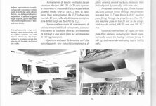
The other issue I encountered with closing up the fuselage was the gaps in the seams. I had to scrape styrene back from each mating surface (especially on the tail) so that all the gaps were sufficiently closed to negate too much filling and sanding. This was compounded by the twist in the fuselage halves that I noted in an earlier post. No matter which way I twisted or pushed the halves around I ended up with alignment issues with either edges or panel lines. I ended up with a bit of an each way bet where nothing aligned perfectly... . You can see from the photos there is work still to be done around the cockpit to get seams and the like ready for fitment of the cockpit.


The other job I have been working on is clearing out the supercharger air intake and the exhaust stubs. I found in references that the intake was pretty much a hollow tube without any dust filters fitted, so I proceeded to drill out the centre once I'd joined the two halves. Other things I noticed in reference photos were that the leading ends of the exhaust stub shrouds were open and in the gap you could see the curvature of the leading exhaust header pipe. The detail is probably overkill, but I like to think its the little details that all add up to making the kit look more realistic once done.


Having done the exhaust shrouds I moved onto the stubs themselves. As you can see they have quite an amount of flash to be removed. I did check to see if there was a raised seam on the real exhausts but all photos appeared to show the seams were ground flat - with a colour variation the only evidence that they may have been two halves welded together.


Once cleaned up I moved onto drilling out the stub ends. I did make an assumption that the exhaust stub from the first cylinders on either side were concealed under the front shroud panel. If this is true then an exhaust outlet should be visible if you look forward along the exhausts - I drilled out a section of the shroud front to represent this hidden stub which you can see in the attached shots.


I do have some more work and photos to post, but I have run out of time today. I will try to put up another post tomorrow with the remaining work done which will bring this thread up to date with my progress.
As always - thanks for taking a look at my project. Constructive criticism, comments and feedback are always appreciated (still learning and experimenting).
Cheers!
Having set up the cockpit I proceeded with the installation of it and the tailwheel well. Sadly both did not sit comfortably within the fuselage - this was expected having done some dry fitting when I had the fuselage and wings mocked up at the beginning. The biggest pain with the cockpit was the armoured head plate. According to the instructions the kit part was to be glued directly above the panel behind the seat. In theory this looked great but the problem was it resulted in the head plate being nearly 2mm too high to fit into the fuselage. I fluffed around trying to re-jig the kit piece but ended up binning it and made one from plastic card (head cushioning yet to be fashioned to fit). Similarly the tailwheel well was great in concept but the only connection to the fuselage was along the joint lines (just above the "molded in place" gear doors) and it was almost impossible to get a proper alignment and a positive fit once both halves were together. I ended up pegging the "box" to the fuselage with a piece of sprue at the top to make sure it was securely fixed in place.
The other issue I encountered with closing up the fuselage was the gaps in the seams. I had to scrape styrene back from each mating surface (especially on the tail) so that all the gaps were sufficiently closed to negate too much filling and sanding. This was compounded by the twist in the fuselage halves that I noted in an earlier post. No matter which way I twisted or pushed the halves around I ended up with alignment issues with either edges or panel lines. I ended up with a bit of an each way bet where nothing aligned perfectly...
. You can see from the photos there is work still to be done around the cockpit to get seams and the like ready for fitment of the cockpit. The other job I have been working on is clearing out the supercharger air intake and the exhaust stubs. I found in references that the intake was pretty much a hollow tube without any dust filters fitted, so I proceeded to drill out the centre once I'd joined the two halves. Other things I noticed in reference photos were that the leading ends of the exhaust stub shrouds were open and in the gap you could see the curvature of the leading exhaust header pipe. The detail is probably overkill, but I like to think its the little details that all add up to making the kit look more realistic once done.
Having done the exhaust shrouds I moved onto the stubs themselves. As you can see they have quite an amount of flash to be removed. I did check to see if there was a raised seam on the real exhausts but all photos appeared to show the seams were ground flat - with a colour variation the only evidence that they may have been two halves welded together.
Once cleaned up I moved onto drilling out the stub ends. I did make an assumption that the exhaust stub from the first cylinders on either side were concealed under the front shroud panel. If this is true then an exhaust outlet should be visible if you look forward along the exhausts - I drilled out a section of the shroud front to represent this hidden stub which you can see in the attached shots.
I do have some more work and photos to post, but I have run out of time today. I will try to put up another post tomorrow with the remaining work done which will bring this thread up to date with my progress.
As always - thanks for taking a look at my project. Constructive criticism, comments and feedback are always appreciated (still learning and experimenting).
Cheers!