Allied Gold-Match (1 Viewer)

Ad: This forum contains affiliate links to products on Amazon and eBay. More information in Terms and rules

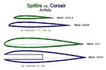
The wing is angled up 4 degrees, and to counter natural lift (which the Spitfire does also) the nose must be angled downward even more to maintain level flight. On the -5 the engine was canted an additonal 2 degrees to provide ven more of a nose down flight attitude.

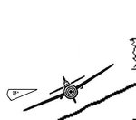
I think you can actually see this in side view photos, though the blue of the paint job does tend to obscure things a bit.

=S=

Lunatic
 
But.... you said "RG, the rudder on the Spit XIV is bigger than that on the Corsair, and the elevator's are about the same." But, as you can see...

RG that illustration is off scale !! The Wing area of the Spit is 22.48m2 and the Corsair's is 29.17m2, giving a roughly similar visible wing area from above(The Corsair's wings are bent remember !)
wich obviously isnt apparent on your illustration !

RG_Lunatic said:
Davidicus,

The F4U flies nose down, and the F4U-4 added a few degrees more attack to make it fly even more nose down, so the airflow is not as disturbed as that of the Spitfire which flies level. Not that this makes much difference.

=S=

Lunatic

RG its the AoA of the wing that counts, and IIRC the Spit's wings has a better AoA than the Corsair's ! (Ever wondered why the Spit XIV's hub is pointing slightly downwards ? ;) )
 
Soren said:
But.... you said "RG, the rudder on the Spit XIV is bigger than that on the Corsair, and the elevator's are about the same." But, as you can see...

RG that illustration is off scale !! The Wing area of the Spit is 22.48m2 and the Corsair's is 29.17m2, giving a roughly similar visible wing area from above(The Corsair's wings are bent remember !)
wich obviously isnt apparent on your illustration !

Okay, I double checked, and you are right the Vought diagram is not in proper proprotions. I was focusing on the tails so I didn't notice that. I've redone it using the USN diagram which is in proper proprotions:

spitfirexiv_vs_f4u-4_surface_comparison_01_174.jpg


The wing area is still not "similar", though it is closer. As for the "bent wing" you are making too big a deal out of this. Yes it is "bent" but only for about the first 4 feet or so are angled moderately down. It was found that because of prop effects this didn't hurt the lift that much and it was important to keep the landing gear short for such a big prop.

f4u_blueprint_frontview_176.jpg


Notice that the span is measure horizontally, not along the wing surface. Still, this has nothing to do with the elevators. As you can clearly see...

spitfirexiv_vs_f4u-4_surface_area_overlay_202.jpg


the Corsair clearly has a lot more elevator area than the Spitfire.

Soren said:
RG_Lunatic said:
Davidicus,

The F4U flies nose down, and the F4U-4 added a few degrees more attack to make it fly even more nose down, so the airflow is not as disturbed as that of the Spitfire which flies level. Not that this makes much difference.

=S=

Lunatic

RG its the AoA of the wing that counts, and IIRC the Spit's wings has a better AoA than the Corsair's ! (Ever wondered why the Spit XIV's hub is pointing slightly downwards ? ;) )

Umm... when the angle of attack is higher the nose points down. To facilitate this you angle the prop/hub UP NOT DOWN! On the F4U-5 the engine and prop were angled up an additional 2 degrees to better facilitate the nose down flight attitude to provide even more visiability over the its longer nose. The AOA of the Spitfire wing is almost exactly level with the fuelage line. The prop is angled down to support its very flat flight attidue, allowing the whole plane to be angled up to gain AoA for the wings. So the Spitfire tends to fly nose up (relatively speaking, the nose may still point down somewhat to counter wing lift during level flight), where the Corsair flies nose down.

=S=

Lunatic
 
RG those drawings are OFF SCALE ! I will however agree that the Corsairs elevator area is bigger, but not by much.

Umm... when the angle of attack is higher the nose points down. To facilitate this you angle the prop/hub UP NOT DOWN!

Oh really ! :)

RG, the AoA is higher when the wings are pointing UP, NOT DOWN ! So the Prop/Hub is tilted DOWN on the Spitfire to INCREASE the AoA of the wing thereby INCREASING the lift !

Lift will increase as the angle of attack is increased up to the point (usually around 17 degrees) where the aircraft stalls, the critical angle of attack.

On the F4U-5 the engine and prop were angled up an additional 2 degrees to better facilitate the nose down flight attitude to provide even more visiability over the its longer nose.

This upwards tilt of the nose and downwards tilt of the wing will reduce lift RG, and try to push the plane down, thus the lift is decreased even further yet ! (And actually Im sure you got it backwards with the Corsairs wings, as its wings were also AFAIK pointed slightly upwards)

About the "Bent" wing;

The bent sections of the Corsairs wings will produce very little lift, and those two section arent small RG, they make up approx. 7-8 sq.m of the Wing area ! Also the intakes on the leading edge in that area further reduces the lift !

Note: Alhtough the "Bent" sections of the Corsair wings will decrease lift, they will also reduce drag, making the Corsair go faster.
 
Soren said:
RG those drawings are OFF SCALE ! I will however agree that the Corsairs elevator area is bigger, but not by much.

The Corsair diagram is to scale. The drawing from which I cut it from gives all the dimensions and a ruler (as shown on the nose view). The Spit XIV diagram - well it was about the only one I could find - but by checking relative measurements for those dimesions I have data for it seems to be right too.

Umm... when the angle of attack is higher the nose points down. To facilitate this you angle the prop/hub UP NOT DOWN!

Soren said:
Oh really ! :)

RG, the AoA is higher when the wings are pointing UP, NOT DOWN ! So the Prop/Hub is tilted DOWN on the Spitfire to INCREASE the AoA of the wing thereby INCREASING the lift !

Lift will increase as the angle of attack is increased up to the point (usually around 17 degrees) where the aircraft stalls, the critical angle of attack.

On the F4U-5 the engine and prop were angled up an additional 2 degrees to better facilitate the nose down flight attitude to provide even more visiability over the its longer nose.

This upwards tilt of the nose and downwards tilt of the wing will reduce lift RG, and try to push the plane down, thus the lift is decreased even further yet ! (And actually Im sure you got it backwards with the Corsairs wings, as its wings were also AFAIK pointed slightly upwards)

That's all fine Soren, but your not getting it. On the Corsair both the wings and the engine are tilted up. This makes the flight line such that when the plane is flying level (at the speed where lift and weight balance) the wings are level, the engine is pulling it strait ahead, and the nose is pointed down.

On the Spitfire the engine is pointed down, which means that when it is lined up on the level, the wings are pointed up, increasing the AoA. The whole plane must be canted up to get this added AoA.

Soren said:
About the "Bent" wing;

The bent sections of the Corsairs wings will produce very little lift, and those two section arent small RG, they make up approx. 7-8 sq.m of the Wing area ! Also the intakes on the leading edge in that area further reduces the lift !

Note: Alhtough the "Bent" sections of the Corsair wings will decrease lift, they will also reduce drag, making the Corsair go faster.

The amount of lift lost by having the inner wing sections angled downwards will be exactly the projection of the vertical component of the normal vector to the wing, which is going to be a loss of only a couple of percent. I doubt there is any reduction in drag at all, since the drag does not care how the lift is being applied.
 
On the Spitfire the engine is pointed down, which means that when it is lined up on the level, the wings are pointed up, increasing the AoA. The whole plane must be canted up to get this added AoA.

RG only the Prop/Hub is pointing downwards on the Spit, while the wings are almost level with the fuselage, pointing upwards only very slightly. When in level-flight the Spit's Prop/Hub will be level, thus because of the Hub's tilt the wing's AoA is increased= More lift !

The amount of lift lost by having the inner wing sections angled downwards will be exactly the projection of the vertical component of the normal vector to the wing, which is going to be a loss of only a couple of percent.

No RG, it is actually a quite substantial amount of lift that is lost by this !

A plane on its side in the air will also loose altitude, and is only descending slowly because of the G forces accuring in the slight turn being created by the lift of the wings.

I doubt there is any reduction in drag at all, since the drag does not care how the lift is being applied.

About the Corsair's "Gull" wings:
The Corsair had a wing bent on both sides of the fuselage, or gull-shaped. This arrangement gave additional ground clearance for the propeller and reduced drag at the wing-to-fuselage joint.
 
Soren said:
On the Spitfire the engine is pointed down, which means that when it is lined up on the level, the wings are pointed up, increasing the AoA. The whole plane must be canted up to get this added AoA.

RG only the Prop/Hub is pointing downwards on the Spit, while the wings are almost level with the fuselage, pointing upwards only very slightly. When in level-flight the Spit's Prop/Hub will be level, thus because of the Hub's tilt the wing's AoA is increased= More lift !

That is exactly what I said. This makes the Spitfire fly in a nose up attidue.

However, the alternative solution is to cant the wings upwards relative to the fuselage, which was done on the F4U corsair (I believe 4 degrees added AoA over that of the prototype), and to cant the engine/prop up a little as well (though not as much). This gives the Corsair a significant nose down attitude when flying "level", which was done to the -1 series to give better visability over the nose when the cockpit was moved aft from the prototype design to facilitate the fuel being removed from the wings and the larger tank placed behind the engine and in front of the pilot. When the -5 came along, with its even longer nose, the thrust angle was raised another 2 degrees.

Soren said:
The amount of lift lost by having the inner wing sections angled downwards will be exactly the projection of the vertical component of the normal vector to the wing, which is going to be a loss of only a couple of percent.

No RG, it is actually a quite substantial amount of lift that is lost by this !

No there is not Soren. The lift lost follows the same rules of physics as anything else... I thought you knew your physics? You sure do refer to it a lot in your arguments for obviously not understanding it. Here's a diagram showing the cost in lift:

f4u_bent_wing_lift_loss_01_186.jpg


The blue vector represents the total force generated by the wing airfoil. The green vector represents the lift force provided in the upward direction. The red line segment represents the loss in lift as compared to an unbent wing. It's as simple as that.

Soren said:
A plane on its side in the air will also loose altitude, and is only descending slowly because of the G forces accuring in the slight turn being created by the lift of the wings.

The inner part of the wings are not angled down at anywhere near a 90 degree angle. And if they were the lifting force of the airfoil would be strait out to the side and thus the projection of the vertical component of the of the lift vector would be 0 thus no lift!

Soren said:
I doubt there is any reduction in drag at all, since the drag does not care how the lift is being applied.

About the Corsair's "Gull" wings:
The Corsair had a wing bent on both sides of the fuselage, or gull-shaped. This arrangement gave additional ground clearance for the propeller and reduced drag at the wing-to-fuselage joint.

Why?
 
No there is not Soren. The lift lost follows the same rules of physics as anything else... I thought you knew your physics? You sure do refer to it a lot in your arguments for obviously not understanding it. Here's a diagram showing the cost in lift:

f4u_bent_wing_lift_loss_01_186.jpg

First off all I hope you'll soon see your mistake here ! Secondly STOP using different scale drawings all the time, and use those you have already used !!

Btw guess how much lift those intakes takes away with them ! ;)

The inner part of the wings are not angled down at anywhere near a 90 degree angle. And if they were the lifting force of the airfoil would be strait out to the side and thus the projection of the vertical component of the of the lift vector would be 0 thus no lift!

RG I NEVER implied the wings were angled anywhere near 90 degree's, I was just making a SIMPLE point wich you obviously didnt understand !


RG_Lunatic said:
Soren said:
About the Corsair's "Gull" wings:
The Corsair had a wing bent on both sides of the fuselage, or gull-shaped. This arrangement gave additional ground clearance for the propeller and reduced drag at the wing-to-fuselage joint.

Why?

RG if you think real hard then you might find something that just doesnt add up. ;)
 
In the mean time here's how Vet pilot Owen W. Dykema saw the F4U-4 Corsair:

In my career in Naval Aviation I flew a number of planes. Except for the twin-engine SNB "Bug Smasher", all were single-engine fighter / attack planes. The best and "funnest" was the Grumman F8F Bearcat. But I got the most flight time, and 47 combat missions off a carrier in Korea, in the Chance-Vought (C-V) F4U-4 Corsair. Its most noticeable characteristic was the inverted-gull wing.

The Corsair had a huge prop, 13 feet in diameter, necessary to absorb the 2200 horsepower of the big Pratt Whitney R-2800 radial engine. The cockpit was designed around the chief test pilot, Boone Guyton, who was 6-ft. 4-in. tall, so there was plenty of room in the cockpit, even for a 6-ft. 3-in.guy like me.

The Corsair was designed largely in the pre-war years, when design competitions tended to emphasize speed over maneuverability. C-V felt that if the wing joined the fuselage at a right angle the drag would be less, and the top speed would therefore be higher. It was that design goal of high speed that led to the long, narrow, cylindrical fuselage and the inverted-gull wing design. It did prove to be 50 knots or so faster than another plane using the same engine (the Grumman F6F Hellcat).

However, in 1939, when war began to threaten, the Navy came to C-V and asked for some modifications that would make the F4U more combat-ready as well. Among those were: (1) move the fuel out of its vulnerable position in wing tanks and put it up in the fuselage; and (2) increase the roll rate and at the same time lessen the stick forces required to roll the plane.

The first design change involved creating room in the fuselage for a 233-gallon fuel tank. To do that C-V pushed the engine forward a foot and the cockpit aft by three feet, and put that fuel tank right in front of the cockpit. That created an exceptionally long distance from the cockpit to the front of the engine, leading to nicknames for the plane like "hosenose" and "hog". As a further result, when the aircraft was in a three-point attitude, taxiing or flying at slow speeds (as in landing), everything in a rather broad angle ahead of the pilot was obscured. Eventually that created, at least for me, for a great deal of trouble landing aboard the carrier.

The second change involved lengthening and broadening the ailerons, which increased stick roll forces, and aerodynamically balancing those ailerons, which reduced those forces. A great deal of experiment and testing went into design of those ailerons. The final design was so heavily balanced that they were very nearly overbalanced. In the latter case the force of wind across the wing alone could cause the ailerons to move, thereby rolling the plane when least expected. One time that nasty characteristic nearly killed me.

The Corsair also had a few other unfortunate characteristics. Because of the high power of the engine and that big prop, there was a great deal of torque on the plane, particularly at slow speed and high power, as in a takeoff or in a waveoff from a carrier landing. A lot of inexperienced Ensigns and 2nd Lt.'s jammed the power on too fast and torque-rolled right into the ground. That led to the cynical "words to live by" (literally), "Low, slow and over you go in the F4U!".

In addition, it had very dangerous spin characteristics, particularly inverted. Especially in the Training Command lots of Ensigns and cadets spun right into the ground from thousands of feet up, unable either to stop the spin or to overcome the resulting high "g" forces to exit the aircraft, leading to the further nickname "Ensign Eliminator". This also led to the endless barracks argument, "In a spin in the Corsair, is it best to keep the power on full, to create strong airflow over the control surfaces, or to chop it off to get rid of the torque?" The only adequate answer always seemed to be, "Don't get into a spin in the Corsair."

In the cockpit the control stick stuck up between your legs and your legs stuck forward into twin "tunnels" that ended in the rudder pedals. On the control stick was a funnel-shaped device called a "pee-tube"(of obvious utilitarian function). On a left console (forward - aft) were the gear, flaps and arresting hook levers, the engine control unit, including throttle, prop (rpm) and mixture ratio controls, the trim tab control wheels and the wing fold controls. On the right console were the radios and circuit breakers. All such fighter and attack planes had to be flown "right-handed".
 
The salient part of this quote is:

The Corsair was designed largely in the pre-war years, when design competitions tended to emphasize speed over maneuverability. C-V felt that if the wing joined the fuselage at a right angle the drag would be less, and the top speed would therefore be higher. It was that design goal of high speed that led to the long, narrow, cylindrical fuselage and the inverted-gull wing design. It did prove to be 50 knots or so faster than another plane using the same engine (the Grumman F6F Hellcat).

First off, the gulling of the wings was not done to increase speed, it was done to allow a large prop to be used while keeping the landing gear as short as possible. This was done to reduce weight while also maintaining the needed strength to land on a carrier.

Second, he implies the reason the F4U was faster than the F6F was because of the angle of the wings joining the body. While the angle of the wings being at 90 degrees might reduce drag very slightly it would not be by much. The angles were chosen very specifically to maximize the strength of the joint at the bend where the landing gear were.

And he further states that they had the same engine, which while technically correct is really wrong. The F6F used a much smaller single stage two speed supercharger, where the F4U used a much larger two stage two speed supercharger, giving the F4U much more power up where the air is thin and maximum speed could be higher.

Finally, the F6F was stubbier and fatter than the F4U, making for more drag and lower speed, and it was a little heavier too.

This is not much of a "source" Soren. Nothing in any of the technical papers I've read about the F4U's development refer to the angle of the wings having been done to reduce drag. If this is your only source for this information... well...

=S=

Lunatic
 
RG_Lunatic said:
This is not much of a "source" Soren. Nothing in any of the technical papers I've read about the F4U's development refer to the angle of the wings having been done to reduce drag. If this is your only source for this information... well...

It wasnt ment as a source RG, it was ment as a view-point ! I can't help that you immediately jump on the part with the decreased drag of the Gull wings, as it wasnt intended to proof this point. However as you just discovered it is obviously aparent that pilots also said it decreased drag, so there's a little extra something to think about.
 
As we all know, pilots are very bad sources for engineering type information. They are known to quote false info all the time. Unless the pilot was a qualified engineer, it's probably hearsay many times removed from whatever the original source was, and totally mis related.
 
Okay, I figured out how to get the airfoils into the windows software so I could provide a comparison graphic. Here there are:

spit_vs_corsair_airfiol_comparison_root_and_15pct_from_tip_180.jpg


As you can see, at the root the Corsair airfoil is thicker and has a sharper rise to the forward edge and its thicker, but it also is more symetrical from top to bottom, which probably makes it a little better at higher speeds and a little worse at lower speeds. The Spitfire wing has almost as much chord at the root as the Corsair wing.

At the the tip the most noticable difference is the relative chord - the Spitfire wing has become rather narrow. Techincally the measurement should be taken at 10% from the tip, however the difference was so extreme I decided to show them scaled against one another at 15% from the tip. To my eye, the tip shapes are very similar, with the Corsairs having its maximum thickness along the top a just a little further back (proprotionally) than that of the Spitfire, but on the bottom it is further back still.

Honestly I cannot tell which airfoil shapes are "better". I suspect they are very similar, with the Spitfire wing generating a little more lift at low speeds but a little more drag (proportionally) at higher speeds, especially near the roots. Next I'll have to figure out how to put these into airfoil simulation software and see if that shows any significant differences.

=S=

Lunatic
 
The gull-wing shape with inboard radiators on the leading-edge by the wing root would possibly offer less drag than the under-wing box radiators on the Spitfire, perhaps ???.........

Gemhorse
 
RG_Lunatic said:
Okay, I figured out how to get the airfoils into the windows software so I could provide a comparison graphic. Here there are:

spit_vs_corsair_airfiol_comparison_root_and_15pct_from_tip_180.jpg


As you can see, at the root the Corsair airfoil is thicker and has a sharper rise to the forward edge and its thicker, but it also is more symetrical from top to bottom, which probably makes it a little better at higher speeds and a little worse at lower speeds. The Spitfire wing has almost as much chord at the root as the Corsair wing.

At the the tip the most noticable difference is the relative chord - the Spitfire wing has become rather narrow. Techincally the measurement should be taken at 10% from the tip, however the difference was so extreme I decided to show them scaled against one another at 15% from the tip. To my eye, the tip shapes are very similar, with the Corsairs having its maximum thickness along the top a just a little further back (proprotionally) than that of the Spitfire, but on the bottom it is further back still.

Honestly I cannot tell which airfoil shapes are "better". I suspect they are very similar, with the Spitfire wing generating a little more lift at low speeds but a little more drag (proportionally) at higher speeds, especially near the roots. Next I'll have to figure out how to put these into airfoil simulation software and see if that shows any significant differences.

=S=

Lunatic

Very nice comparison RG ! (Seriusly !)

However your forgetting that the root profile of the Corsair's wing is the one wich is tilted and has those two intakes ! (Both factors decrease lift by a big margin !)
 
Soren, the intakes do not reduce lift that much, they are at an inefficient part of the wing. The part of the wing near the root receives a boundary layer effect off the fuselage and a turbulent effect off the prop. If it had been a huge issue they'd have moved the cooler inlets to the nose or scooped them from under the wing (like the Spitfire) or fuselage. You seem to think that the Vought (and Yakovlev) engineers were stupid.

As for the loss of lift for the angle, I've shown you how much is lost and it's negligable - a few percent that's all.

On top of that, airfoil cross-sections are taken vertically anyway.

Both those factors reduce lift by a tiny margin over a very small area.

=S=

Lunatic
 
Soren, the intakes do not reduce lift that much, they are at an inefficient part of the wing. The part of the wing near the root receives a boundary layer effect off the fuselage and a turbulent effect off the prop.

No RG, infact the intakes take away alot of lift ! Look at my little modification of your comparison at the bottom of the page. A good amount of airpressure is lost on the wing hitting that leading edge area !

If it had been a huge issue they'd have moved the cooler inlets to the nose or scooped them from under the wing (like the Spitfire) or fuselage.

No cause they were looking for less drag RG ! As a result the fuselage was shaped circular and the wing shaped bent and inverted.

From: Bent-winged Bird to Whistling Death
-and the Vought team turned to an inverted gull wing for two reasons. First, the landing gear could be mounted at the low point or "knuckle" of the wing, thus reducing the length of the landing gear struts, while still providing ground clearance for the big propeller. Second, the wing joined the circular fuselage at nearly a right angle, reducing drag and eliminating the need for bulky fairings.

You seem to think that the Vought (and Yakovlev) engineers were stupid.

No RG, but in those times alot of mistakes were made in aerodynamics, wich also should be obvious to anyone.

As for the loss of lift for the angle, I've shown you how much is lost and it's negligable - a few percent that's all.

I can see you still havent realized your mistake yet.
 

Attachments

  • spitfire_vs_corsair_airfoil_comparison_180.jpg
    spitfire_vs_corsair_airfoil_comparison_180.jpg
    32.5 KB · Views: 2,745
The 90deg attachment of the wing had the benifit of eliminating the root fillet to reduce the drag at the attachment point. The drag from this point is created by the turbulence caused by dissimilar airflows meeting at that point and is greater at any other angle. If this drag/turbulance is to great it can effect the stabilizor/elevator as well as the speed of the aircraft.
 
Soren said:
Soren, the intakes do not reduce lift that much, they are at an inefficient part of the wing. The part of the wing near the root receives a boundary layer effect off the fuselage and a turbulent effect off the prop.

No RG, infact the intakes take away alot of lift ! Look at my little modification of your comparison at the bottom of the page. A good amount of airpressure is lost on the wing hitting that leading edge area !

Your diagram shows the intake both too large and set too high on the wing. The following diagram is approximately accurate (I cut away the wing diagram and re-oriented it to position the inlet):

spit_vs_corsair_airfiol_comparison_root_and_15pct_from_tip_02_190.jpg


As you can see, the inlet is both smaller than the one you depicted (relative to the thickness of the wing) and more importantly it is located lower along the leading edge. The air has to go somewhere. Pressure in the scoop will cause some of the air approaching the front of the inlet to flow around the wing, giving back some of the lift. Air traveling through the wing also gets heated and then vented restoring a little bit of the lost lift.

Yes there is some loss of lift, but it is no where near as signficant as you are making it out to be. If it was, Vought had pleanty of opportunities to move the scoops in the -4, -5, or -7 variants - they did not.

Soren said:
You seem to think that the Vought (and Yakovlev) engineers were stupid.

No RG, but in those times alot of mistakes were made in aerodynamics, wich also should be obvious to anyone.

Even today this is considered one of the better places to locate scoops, it is just inconvienient for plumbing reasons.

Soren said:
As for the loss of lift for the angle, I've shown you how much is lost and it's negligable - a few percent that's all.

I can see you still havent realized your mistake yet.

LOL - point it out to me.

Here's the loss of lift due to the angle of the wing (shown in red):

f4u_bent_wing_lift_loss_magnified_01_521.jpg


That's about 6.25%.

=S=

Lunatic
 
RG,

Look at the pic below, now tell me, what happens to a plane flying like that ?
 

Attachments

  • angles25_936.jpg
    angles25_936.jpg
    8.9 KB · Views: 422

Users who are viewing this thread

Back