Navigation
Install the app
How to install the app on iOS
Follow along with the video below to see how to install our site as a web app on your home screen.
Note: This feature may not be available in some browsers.
More options
You are using an out of date browser. It may not display this or other websites correctly.
You should upgrade or use an alternative browser.
You should upgrade or use an alternative browser.
British Lancaster Dambuster Rack
- Thread starter Micdrow
- Start date
Ad: This forum contains affiliate links to products on Amazon and eBay. More information in Terms and rules
More options
Who Replied?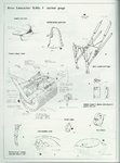
Interesting! I don't have anything more on it but Lanc should have something.
FLYBOYJ
"THE GREAT GAZOO"
Looks pretty accurate to me!


R-2800
Senior Airman
yeah it looks normal to my knowledge
the lancaster kicks ass
Major General
- 19,931
- Dec 20, 2003
other than the weights given the only extra dimensions you need are the 60inch length and 56inch diammeter, dimensions imposed on wallis by the RAF, other than that i believe that yes the motor to rotate the mine (remember she is a MINE NOT A BOMB!) should be placed further forward as i've always understood it...........
blue_halloween
Airman
- 33
- Mar 2, 2007
the hydraulic motor was supplied by the bomb bay door hydraulics... there wernt any doors so....it was an ideal solution .
blue_halloween
Airman
- 33
- Mar 2, 2007
release mechanisum was supposed to be spring loaded.. god knows how? if you read the sketch it says it.... the springs were trying to push the arms apart and were being held inplace by a bomb release mechanisum. lengh of the mine was just under 60 inches because 60 exactly would,nt fit inbetween the release calipers the mine had a dia of 50 inches in its final version .Hydraulic pump was a vickers standard unit, would you belive normally fitted to the steering controls of a submarine ?? lol
The illustrations are interesting. Thanks.
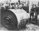
The only other detailed illustration of the Dambuster bomb rack with some credibility I found so far is on SAM Publication's THE AVRO LANCASTER, on p. 115. According to the book this was from German investigation documents and mechanisms attached to the rack is reasonably well drawn.
The only other detailed illustration of the Dambuster bomb rack with some credibility I found so far is on SAM Publication's THE AVRO LANCASTER, on p. 115. According to the book this was from German investigation documents and mechanisms attached to the rack is reasonably well drawn.

- Thread starter
- #13
Wuerger190
Airman
- 26
- Nov 19, 2007
And you were right. Some people just don't use their eyes... let's hope they're not pilots!So Lanc and I both agree something is odd about the placement of the rotation motor unit...
")
Users who are viewing this thread
Total: 1 (members: 0, guests: 1)