I'm doing a CAD model of a Packard V-1650-7 Merlin engine for fun and thought I'd share the progress. (1 Viewer)

Ad: This forum contains affiliate links to products on Amazon and eBay. More information in Terms and rules

rtwpsom2

Airman
42
52
May 21, 2013
I haven't had a lot of time to do something fun like this so I've actually been working on the project on the side for a couple of years now and haven't made tons of progress, but with covid and losing my job I have more time for it, so I have enough to actually show off a little. The model itself and the rendering are done in SolidWorks. The drawings are from AircorpsLibrary. I've completed 3 top level subassemblies now and am working on the fourth. This one is the largest and most complex I've worked on in the project so far. I'll post each one individually so as to make things easier to delineate, but the images are kinda large, so just a heads up.

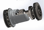
The first project I did was the starter, it was done back in late 2018. The only parts that are missing are the windings (or a reasonable facsimile of them) because I didn't have a drawing for them. There is a part number and drawing for them, I just didn't have a copy. I'm also missing the nameplate because I didn't want to deal with creating a decal wrap for the surface. I'll probably them some day IO have more time... oh... wait. :tongueclosed: teehee

If any of you know anything about solidworks, and cad in general, they don't do gears very easily. I had to learn a lot, it was a steep curve, but I can say these gears are machinable models. (kinda proud of that fact)

0005.JPG 0004.JPG 0003.JPG 0007.JPG 0002.JPG

Give me a few and I'll get the rest of the subassemblies posted.
 
The next assembly is the started engagement mechanism. It's a clutch mechanism that acted like the solenoid on a modern starter does now, it clutches to engage the starter motor to the crankshaft when it's starting then declutches to allow it to free spin and pull back the engagement slide. I have a little video of the gears in motion to show how they mesh, if I can figure out how to post it, I'll add it in, it's like porn for CAD jockeys.

609970a.jpg 609970b.jpg 609970d.jpg 609970e.jpg 609970c.jpg
 
The third assembly is called the Magneto Drive Assembly. It's little more than a drive shaft that takes power of the crank and transfers it to the magnetos, kinda like how the distributor in a car engine has a shaft that usually goes down to the oil pump or crankshaft to drive it and keep it in time. Because the Merlin has two magnetos, one for each cylinder bank, this sits in the middle of the wheelcase and outputs to both sides of the wheelcase. It's also sitting in a cup that acts as an oil bath for the main gear.

610136A.jpg 610136A.jpg 610136.jpg
 

Attachments

  • 610136B.jpg
    610136B.jpg
    129 KB · Views: 51
Now the last one is more impressive. I got tired of doing little piddly things and bit off entirely too much to chew. This is the upper crankcase assembly. The lower crankcase is nothing more than the oil pan and oil pump, so it's not like there is a ton left to crankcase aside from this assembly, but the title of the drawing says upper crankcase so it's the upper crankcase. So far I have only been working on the cylinder head mounting studs and the crankcase casting itself, but once you look at it I think you'll understand why it has been taking me so long.

This is actually the third iteration of the model of the crankcase. Each time I spent forever just trying to figure out how all the various parts interact with each other and after about 200 or 300 features I figured out there was a better way I could have done it. So twice now I've scrapped the whole thing and went back to zero and restarted the model. That may sound like a huge waste of time, and maybe it was, but the model is a much leaner and meaner (and far more accurate) beast now because of it. So some of these pictures are actually of earlier iterations than the current one. Here are some in progress pics, wit the last couple being renders of how it looks right now.

610995-01.jpg 610995-02.jpg 610995-03.jpg 610995-04.jpg 610995-05.jpg 610995-06.jpg 610995-07.jpg 610995-08.JPG 610995-09.JPG

Oh, and I got really bored with adding fillets at one point so I modeled the crankcase to cylinder head connecting studs, of which there are three types.

studs.jpg

So that's where I'm up to so far. I hope to continue working on it and posting about it. I have created a blog, if that's still a thing these days, but if you are curious and want to see the models themselves I post my work to grabcad, a CAD model sharing site. You can go on there and download the models and see them yourself.
 
WOOHOO!!!! The crankcase is done!!!! After about a billion holes and a lot of other machining the part is complete. I decided to do a couple of renders to celebrate.

BwD9uOF.jpg

j6MHRqZ.jpg


I also played around with the materials in a few renders, but here's what I settled on.

F4p1X0D.jpg


I did a little work on the BOM as well, so it looks like next up I will be doing several of the main bearing cap studs.
 
LOL, did the cute table cloth stay with it?
 
When the CAD model is complete will you be going into series manufacture?

There are enough castings out there in the shops that I doubt anyone would need to start up production on casting new parts any time soon. I might try my hand at 3D printing some parts, tho.
 

Users who are viewing this thread

Back