P51 D Antenna Wire

Ad: This forum contains affiliate links to products on Amazon and eBay. More information in Terms and rules

Crimea_River

Marshal
45,079
13,131
Nov 16, 2008
Calgary
Hi all,

I'm sure this has probably been discussed ad nauseum somewhere but my search has come up inconclusive.

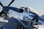
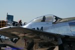
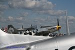
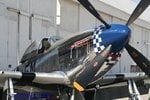
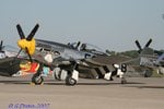
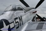
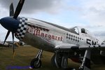
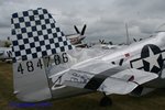
I'm trying to figure out whether I should include an antenna wire on my P51 D-5. Some references show antenna wire from top of tail fin to back of seat head rest thru the canopy hood for the SCR-274N radio set on a later model D-20 machine. A study of many photos show some Mustangs with and many without but the ones with the wire all seem to be later model and post war machines.

Can anyone give me the low-down on this wire? When was it used? Which models or time it was introduced?

Thanks a lot.
 
An intersting one CR. So far, I haven't seen any pics of WW2 P51D's with the antenna wire actually fitted! I honestly don't know the real answer, but I suspect the use of later VHF radios negated the requirement for the antenna wire, with the mast incorporating the element, as per later Spitfires before whip aerials.
I asked a RAF ex-Mustang pilot, who'd flown both the P51B/C (Mustang III) and the 'D' (Mustang IV), and he told me his 'D' model did not have a wire.
On all my models of the 'D', I haven't included a wire, having studied close ups (where available) of the canopy and rear of the armoured plate of the head rest.
However, I'm sure that someone will have the info, probably Bill (Drgondog), and I'd be interested to learn more too.
 
Well, here are a couple of photos of WW2 machines showing the wire:

Can't see the wire but if you look closely, the spring attachment on the top of the tail that holds the wire is quite visible.
_2398_Mondolfo_March_1945_colour

p51_mustang_p27.jpg

p_51_9.jpg


I have some others in books (too lazy to scan) but I agree with you that most do not have the wire. However, the Mustang manuals show a wire in diagrams of both early and late radio set installations and it seems that wires show up MORE in post war machines flying in Korea.

Looking forward to hearing more on this.

Thanks!
 
Me too! BTW, only in the last pic can I only just make out a wire mounting tensioner - probably just the repro on screen. I did notice though, that the shots are of 15th AF (?) aircraft, Italy based? Maybe radio transmission requirements there required a different aerial set up - all the pics I refered to earlier were 8th AF, in the UK.
 
Dont know if its any help, but Geraldine, Aint Missbehavin, and Cripes A Mighty 3rd either have, or the canopy mods to have fitted, this particular bit of offending wire. One of the pics shows the internal springs from the headrest. I might some more shots, I'll have a look later on.
 

Attachments

  • IMG_2908.jpg
    IMG_2908.jpg
    63.4 KB · Views: 3,287
  • IMG_2401.jpg
    IMG_2401.jpg
    57 KB · Views: 912
  • IMG_2585.jpg
    IMG_2585.jpg
    58.3 KB · Views: 892
  • IMG_2594.jpg
    IMG_2594.jpg
    81.5 KB · Views: 1,389
  • IMG_3265.jpg
    IMG_3265.jpg
    62.4 KB · Views: 802
  • IMG_3286.jpg
    IMG_3286.jpg
    57.9 KB · Views: 794
  • IMG_3284.jpg
    IMG_3284.jpg
    64.1 KB · Views: 1,317
  • IMG_3279.jpg
    IMG_3279.jpg
    69 KB · Views: 913
  • IMG_3488.jpg
    IMG_3488.jpg
    63.2 KB · Views: 825
Last few. Sorry, but I have no idea what D model variants these A/C are.
 

Attachments

  • IMG_0269.jpg
    IMG_0269.jpg
    66.6 KB · Views: 692
  • IMG_0278.jpg
    IMG_0278.jpg
    72.4 KB · Views: 684
  • IMG_0268.jpg
    IMG_0268.jpg
    76.5 KB · Views: 1,322
  • IMG_1322.jpg
    IMG_1322.jpg
    59.7 KB · Views: 806
Some great shots there Gary, and useful stuff, it it proves the wire was fitted.
One of the problems with restored warbirds, is that the owners very often go to great lengths to get the aircraft as authentic as possible. Unfortunately, this sometimes results in a piece of equipment being fitted that wasn't on the particular aircraft depicted, during it's service in WW2, but might well have been on others of the same type!
I once built a Spit Mk IX for a friend who had flown one in late 1944 (since deceased unfortunately) and faithfully reproduced the aerial wire, from mast to fin, which, until then, I thought was standard. Although delighted with the model, he did tell me that the radio fit used by his Group no longer used the wire antenna!
There is no way that I am disputing the fit of the wire on P51D's, but I have seen so many pics, including close-up shots, were there is no sign of the wire, and some of these have had the canopy fairlead opening too.
It could well be there were different mountings dependant on equipment fit, as I know there were on the P51B/C during its service life, but it really would be interesting to get some solid info on this subject.
 
8th AF Fighter groups did not (AFAIK) use anything but ARC-3 command radio mast on ANY model D/K model. Ditto B/C except the Malcolm Hood mod imposed a Whip antenna a little further aft than the standard B Mast antenna to accomodate the sliding canopy.

EDIT - the 15th AF 51B/C did have antenna wire..

I also don't recall any 8th AF P-47 antenna through the canopy on the -25 and beyond.

Just talked to a 355th CC who stated that the SCR 522 came with all the -5's the 355th had, although the rarlier SCR-274 Command Radio used the wire range receiver. Eighth AF SOP was to use the SCR 522 for both B and D model's until the introduction of the P-51D-30 and all P-51H.

The latter had tail warning radar plus Twin masts for ARC-3 command radios - so what you see post WWII/ANG/Korea will frequently have antenna wire.
 
Thanks very much Bill. I thought you'd have the answer! It's good to know that I've got my 8th AF Mustang paintings and models right, after all these years of harbouring very slight, but nagging doubts!
 
Thanks everyone for your help. I agree with Airframes that you can't rely on restored birds for this type of stuff.

I'm modeling a 15th AF subject in Italy summer 1944. Mustang D-5. I'm going to go with no antenna wire as that's what most of the photos seem to indicate.
 
Antenna length is based upon broadcast wavelength (for a huge simplicity in statement).

VHF radios today are line-of-sight and only have a 260m range. Most all are blade antennas. I've often asked the question and have never received the answer, but suspect that many wire aerials might have been for HF transceivers. HF has ability to propogate by bouncing off of the ionosphere and thus can achieve MUCH greater beyond-line-of-sight comm. Today this can be thousands of miles in distance.

Early VHF tranceivers had average ranges of 60m. I suspect that the early WWII aircraft with long aerials were HF coinciding with their long boradcast wavelengths to achieve comm links at max mission radius. As the war progressed and technology marched on, VHF likely became more efficient. Perhaps this is the reason that mast mounted (blade type) antennas became acceptable for most european operations. For pacific operations, HF likely continued to be necessary due to long distances involved.


Good observations. Eighth AF doctrine had a radio relay flight over the channel to maintain a command link from Type 16 and other UK based com nets to the escort commanders..
 
Thanks everyone for your help. I agree with Airframes that you can't rely on restored birds for this type of stuff.

I'm modeling a 15th AF subject in Italy summer 1944. Mustang D-5. I'm going to go with no antenna wire as that's what most of the photos seem to indicate.

A lot of the canopies on restored birds are late model canopies from National Guard, Reserve and Post WWII 51's.

The dash numbers that came home were -15 and above. most of the -5 and -10's (and nearly all of the P-51B/C)were scrapped between July and October 1945. Some of the -20 and -25 were sold to Switzerland but most came home.

Almost all the ones that came home were upgraded to -30's. The -30's came from factory with antenna wire and you see the factory 'hole' in the canopy in many of the photos above.

When trying to decide which receiver type was used from one of the WWII photos - go immediately to the tail and look for the spring tensioner at the top of the vert stabilizer - you can see it but frequently not the actual antenna wire itself.
 
Good stuff again Bill, thanks. I's forgotten to mention the radio relay aircraft, and the 'repeater' ground stations.
Matt, you're bang on. Without disclosing 'where, when, why', etc, I have in the past used certain radio equipment where, depending on geographic location and time of day, and where the transmission is 'going to', an 'external source' antenna has had to be used. This quite often meant calculating the antenna length to accommodate the above requirements, and stringing-out the wire, for example up, and between, two trees. In areas devoid ovf vegetation, this could get quite , er, interesting!
 
I'm New to the Warbird Forums and while doing some research for the Mustang ran across you Post concerning The antenna's.
Since I'm building an RC 1/7 th scale mustang I try to research any details I can to aid in the building. I ran across this Flight manual a Few Months ago and thought it might be of use-

P-51 Mustang Pilot's Flight Manual - Google Books

Look at the tech section of this forum - we probably have one that could be uploaded.
 
I'm New to the Warbird Forums and while doing some research for the Mustang ran across you Post concerning The antenna's.
Since I'm building an RC 1/7 th scale mustang I try to research any details I can to aid in the building. I ran across this Flight manual a Few Months ago and thought it might be of use-

P-51 Mustang Pilot's Flight Manual - Google Books

Smitty - if you are doing an 8th AF Mustang you won't need the antenna wire through the canopy to the tail.
 
This is an interesting question I have looked into and discussed with a number of people who have expertise in the area.

Most U.S. control towers were set up to transmit on 268 KHZ for the purpose of giving landing and takeoff clearances to aircraft. So even light aircraft were equipped with receivers for the frequency range 200-400 KHZ, even if they had no transmitter. For this reason, when the USAAF adopted the SCR-274N "Command Set" receivers and transmitters early in WWII, a standard equipment set consisted of a BC-453 receiver for 190-550 KHZ, a BC-454 receiver covering 3-6 MHZ and a BC-455 for 6-9.1 MHZ, together with a couple of transmitters, enabling coverage of both the AN Range as well as the standard control tower frequencies and other required military communications. This equipment required a long wire antenna, typically sting back to the top of the tail.

When the USAAF got to Europe, it found that the RAF had adopted VHF for fighter aircraft communications, using a crystal controlled set known as the TR1143. The Americans had to be compatible with the British when it came to fighters, and VHF gave far superior short range communications anyway, so the U.S. built the British set as the SCR-522, and adopted it as the standard radio for fighters, at least in Europe.

VHF was a big advancement but it caused a bit of a dilemma, especially for fighters operating in the U.S., which had to still use the AN Range for navigation. Fighters flown in the U.S., at least, had to have the low frequency receiving capability. Problem was, the SCR-522, while no more bulky than the SCR-274N receivers, transmitters, and modulator, still took up virtually all of the available room in the aircraft. Also, the fighters deployed to Europe would not necessarily require the low frequency capability, so an easy add-on capability was desirable to keep things as standard as possible.

The answer to this problem were the Detrola Model 438 and the BC-1206.

Both the Detrola and the BC-1206 were designed to operate directly from 24VDC, without a dynamotor, and to be set up so that they could fit into a standard aircraft 3 inch instrument panel hole. They were small enough to be mounted directly in the cockpit with no more than a power lead and an antenna connection. Using their headphone jack, the sets could be plugged directly into the same audio circuit used by the SCR-522, so switching between radios was not required. They could be installed or removed within minutes without affecting the VHF installation.

The Detrola went into the later model P-38, P-51, P-47, and some P-63's, fitting right into the cockpit, possible because the remarkably small receivers were only about twice the size of the control boxes used for the larger radios. The P-51 and P-47 had the little set right next to the pilot's seat, facing upward at an angle, while on the P-38 it was to the right of the pilot's seat, almost resting on the floor, facing up. On the P-61 it was in a rather strange installation behind pilot's right shoulder, the dial facing forward. The P-63 manual I have describes the Detrola as a "portable" installation, even though it is bolted down under the main radio panel at the bottom of the instrument panel and the P-38 manual says the Detrola "may still be installed." Presumably this indicates the possibility that the set was yanked out when the aircraft was deployed overseas. Interestingly enough, none of these installations used the set's ability to be installed in an instrument panel hole. All installations used long wire antennas; on the P-51D, the Detrola antenna is the long wire coming through the hole in the top of the bubble canopy and stringing back to the tail. The AN-104 mast that was the actual antenna used for the SCR-522 also was used to hold the long wire antenna and was insulated from the wire antenna.

In Europe, while US fighters did not use the LF band for communication but we do know they used radio beacons associated with their home fields for navigation. So at least some of the P-51's and P-47's appear to have been equipped with the Detrola/BC-1206 for that purpose, along with a long wire antenna.
 

Users who are viewing this thread

Back