Stripped down Mosquito MK IV 1/32

Ad: This forum contains affiliate links to products on Amazon and eBay. More information in Terms and rules

Just binged through this thread and wow is all I can say sir just wow! :pilotsalute:

My late father would have wanted to be yours and Crimea_River Crimea_River 's best friend the man lived and breathed the D.H. Mosquito and was a long time volunteer at Salisbury Hall home to the Mosquito Museum.

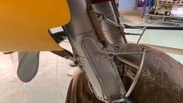
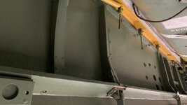
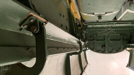
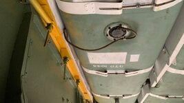
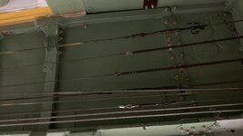
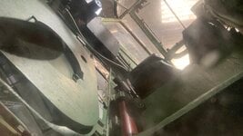
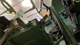
Last year I was lucky enough to have a taxy ride in HJ711 and a sit in experiance in the XVI at the Mosquito Museum (I know they rebranded but if you look it up on the web you still get taken to the same website!) and during the tour around the 3 Mosquitos in residence I gained some close up access to the Prototype hopefully these photos may be of some use?
 

Attachments

  • 20211128_130522370_iOS.jpg
    20211128_130522370_iOS.jpg
    847.3 KB · Views: 37
  • 20211128_130610045_iOS.jpg
    20211128_130610045_iOS.jpg
    1 MB · Views: 38
  • 20211128_130613692_iOS.jpg
    20211128_130613692_iOS.jpg
    777.8 KB · Views: 37
  • 20211128_130615423_iOS.jpg
    20211128_130615423_iOS.jpg
    1 MB · Views: 36
  • 20211128_130647120_iOS.jpg
    20211128_130647120_iOS.jpg
    1 MB · Views: 35
  • 20211128_130730114_iOS.jpg
    20211128_130730114_iOS.jpg
    905.9 KB · Views: 36
  • 20211128_130744152_iOS.jpg
    20211128_130744152_iOS.jpg
    1.2 MB · Views: 37
I know Andy, would be appriciated, but till now Iám just busy with the tailsection and a bit at the cockpit. Maybe I'll rebuilt the cockpit as well with printed parts (maybe I can made a very exclusieve kit :) )
But pics from the wing/fuselage construction on the inside and details of the decks above the wing and behind the radio's would also great
I've find some solutions to the made the hull strong but very visible for the inside
 
Had to do something last weekend
When drawing the stabilizer and rudder surface I found out that the frames 6 and 7 were too far from each other, it was 9 mm apart and that is quite a lot, so I had to take the whole thing apart again and replace the tie rods with a 6 mm shorten. That in itself is a no-brainer, but I had to demolish a well-functioning thing and hope that I could put it back together properly

19b0861aa808028b8d4cef4a9c71d7c9.jpg

So I had to put a new shot in between

I printed out the stabilizer plane and rudder to see how I should make the hinges, to scale hinges would be too fragile, so I came up with a slightly different solution

2e67d5bb049aa729a60ed5d3de779f37.jpg


Yep, that rock stuff keeps getting warped, I have to think about how I can prevent that, it already happens during printing. The rudder surface itself is not completely correct yet, the top should be a bit flatter and the whole a little narrower

But "time wears out with trial and error" is an old Dutch saying, but it is true. It all seems simple, glue a few cans together, but I did have some fun with it, but once put together it's pretty neat

b7f9dd5992587de99e11b9b94a5ec273.jpg


Then came the next step, mounting the parts, which is actually a puzzle in itself, truss 6 okay, matter of gluing it with the stabilizer surface, but truss 7 has to be glued to the stabilizer surface, the rudder shaft must be inserted into the rudder surface at the same time and the tie rods must then be adjusted to neutral. But first the stabilizer and stirring surface must first be combined. In retrospect it should have just used 1 long rod. There is one thing I don't quite understand. In the sketches the pivot point is more towards the back, but then the rudder plane turns with the front out of the stabilizer plane, but I don't know how that works in real life, because I don't see that in the photos and sketches

But then........................................ with taking these two pictures did i see something

95c00a9df39d731f4905cc4eda0669df.jpg


c11bd1946221270f7d0e894f130e4f20.jpg


It looks good in itself, just warm up the surfaces and straighten them, but I saw that I had mounted the wrong rudder surface, the correct one was printing. SH*T ............breaking apart is not an option, because I destroy much more than I like. So I will have to adjust the rudder surface in this condition, so that sucks a lot, but okay, then some old school scratching again
 
...... There is one thing I don't quite understand. In the sketches the pivot point is more towards the back, but then the rudder plane turns with the front out of the stabilizer plane, but I don't know how that works in real life, because I don't see that in the photos and sketches

Hi Bert. Regarding your question about the pivot point, the leading edge of the rudder actually deflects outwards from the plane of the stabilizer because the hinge point is inside the rudder. The picture below of out Mosquito shows the rudder slightly deflected and you can see that the rudder leading edge has shifted outward.

image006.jpg


If that isn't clear, I can get a better shot next weekend if you need it.
But pics from the wing/fuselage construction on the inside and details of the decks above the wing and behind the radio's would also great
I've find some solutions to the made the hull strong but very visible for the inside

This video might be helpful with regard to wing/fuselage construction:


The deck behind the cockpit is actually the upper surface of the wing and the equipment in this area varied somewhat between marks. I'm not sure that I have info for the B.IV but I do have lots for the B.35. I will need more time to throw something together on this as there is no one picture that I think will make this area clear.
 
Amazing, simply amazing. Taking on a project like this is certainly a challenge, and one that is going very well.

In my scanning through the pages, probably to fast, I did not see and reference to the platform that you are using for the designs and what printer make/model for creating the parts? Mind sharing?
 
Thanks again Andy
Yeah, in my digital simulations, I had seen the leading edge (nice, I always learn new words in englisch) was outcoming, but when I see the hinges the used, it;s not clear how it possible to turn out on 1 pivotpoint, It's possible when the hinges has a connection rod with two turn points so the rudder can move sidewards.
I won't change the model, normally the rudder will be in neutral and it's only moveable to see how the pedals are moving in the cockpit. But to understand the subject and the details so I can explain things why I do something or just let it is very important. Pics and movies are always welcome, I ahve a lot of reference but never to much. On the tailsight there is very less to find details, cockpit and weapons are mostly well documented.


Ralph Haus Ralph Haus
Thanks, well, I do not realize the whole proejct, maybe I'm lucky, because when I knew all the work, I didn't start :)

I thaught I had share info of the digital stuff and printing but..................

I'm using Solidworks as a basic user, I know the basis things, and search on the web when I needed something special how to do. I've learned it all by myself by desinging a kinda kit of a dutch armyvehicle.

Printing is something I always wanted, but you know, expensive, unknown stuff, but in last december I bought two secondhands printers to play with it, learned a lot, made a lot of faults but for a couple of months ago I decided to buy a Elegoo Mars 3 Much quicker then the old Anycubic. I'm printing with the Elegoo waterwasable resin, because I've to do into the house and with all the IPA / Isopropanol, it's smelly and dangerous. When printing, you don't smell the resin.
I wash the models just with water in a wash&cure installation, so the enverioment is save :)

Don't know how the resin will act after a couple of years, maybe very breakable, well, I ahve start again maybe, I've all the files (same story as Bulder2010 )
 
..... I ahve a lot of reference but never to much. On the tailsight there is very less to find details, cockpit and weapons are mostly well documented.

Hmm, that "Englisch" again. Not sure what you mean by "tailsight" but just in case, here's a poor pic of the tail attachment structure exposed. Unfortunately, ours is not together yet so I can't get a good picture of it.

20191227_215616.jpg
 
Ha Andy
Dont get exactly the meaning of "Englisch" but I suppose you mean my poor englisch writing and using the wrong grammar? :)

No, "tailsight" is a dumb mistake. I mentioned "tailside" i.e. the tail is often not detailed described in reverence books

The pics are clear enough, the more I learned, the easier it is to understand the stuff.
But, it's still not really clear how the edge can come out when using this kind of hinges

e40e2d07f52118067c3f8d80cd07e2be.jpg


Airframes Airframes
Thanks, the second pic is great for the horns of the elevatorbackside

SaparotRob SaparotRob
yeah, agree. On other fora there is no this kinda special knowledge
 

Users who are viewing this thread

Back