Tamiya 1/48th Mustang III

Ad: This forum contains affiliate links to products on Amazon and eBay. More information in Terms and rules

FlexiBull

Airman 1st Class
279
0
Feb 9, 2009
Not sure were to post this as it could equally go in the "Aviation technical" section.

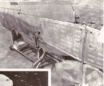
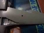
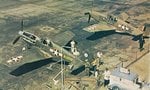
I know there are several faults with this kit, namely the wheel well/main spar issue, but my question is this, did the actual Mustang III/P 51C have a single large spent cartridge ejection chute?

P1020553.jpg


I have been unable to find a good underside plan for the P51C I've got plenty for the P51D.

Thanks
 
Sorry my reply is useless to you on this question. And I'm sitting here next to a calender with a beautiful full-color photo of a restored Mustang in flight. A P-51D, of course. I actually have a question for you:

I notice on the 3-way drawings of this Mustang that there is a panel line going down the center of the fuselage. I assume this is the same on the P-51C. Are you planing on scribing that panel line after you've filled and sanded the joint between the fuselage halves? I'm asking this because I've been working on a G3M Nell that has a panel line down the center of the fuselage as well. I'm looking for excuses to not have to scribe this line, and I'm hoping you're going to say, "No, don't bother with that. I'm not going to, so you don't have to either."

Anything to get out of that unpleasant bit of work...
 
In the pic of the crashed P-51B of 364 FS of 357 FG (Kagero book P-51B/C over the Third Reich) the single large spent cartridge ejection chut is seen clearly ALso there were two smaller ones ( red marked in the pic below). P-51D had three ones here.
 

Attachments

  • p-51c.JPG
    p-51c.JPG
    52.7 KB · Views: 208
How about THIS one for a project P-51!!!!!!!!!!!
http://www.wwiiaircraftperformance.org/mus...p51b-12093.html
I also have some info on the wings from another forum, a lot of text, but interesting about wing and gun configurations from A to D models. I will make post another reply including it. cheers, Bill "According to Gruenhaggen's tome, a British Mk III (FX953) was fitted with a three- bladed unit (see photo page 131). It appears to be an Aeroproducts blade profile but sits noticably farther aft in the spinner than those fitted to Xp-51F and that seen in Martin's image above. Can a positive ID of either be made?" from another reply
 

Attachments

  • IceCream_truck3.jpg
    IceCream_truck3.jpg
    90.1 KB · Views: 196
Last edited:
Thanks for your help guys, I now know that this is one issue I don't need to deal with.

Bill nice website but for some reason I can't get some of the images to open.

Wurger how did you stick those red marks on my model :D thanks for the accurate info, as always.

Flexi
 
This is what the underside of the wing looked like.
 

Attachments

  • scan0009.jpg
    scan0009.jpg
    352.5 KB · Views: 187
That is a very good image just what I needed. Also the bomb rack details.

Thanks Guys
 
Sorry my reply is useless to you on this question. And I'm sitting here next to a calender with a beautiful full-color photo of a restored Mustang in flight. A P-51D, of course. I actually have a question for you:

I notice on the 3-way drawings of this Mustang that there is a panel line going down the center of the fuselage. I assume this is the same on the P-51C. Are you planing on scribing that panel line after you've filled and sanded the joint between the fuselage halves? I'm asking this because I've been working on a G3M Nell that has a panel line down the center of the fuselage as well. I'm looking for excuses to not have to scribe this line, and I'm hoping you're going to say, "No, don't bother with that. I'm not going to, so you don't have to either."

Anything to get out of that unpleasant bit of work...

I may be too late here but there is only One CL 'panel' line - namely the engine cowling above the Merlin and only from nose back to the aft engine inspection panel (which was a 'wrap around') in front of windshield. The engine cowling is a split clamshell with Dzus fasteners.

The only other CL seam is where the wings are joined.

Could be what you saw was a drawing in which a.) antenna was displayed on top side, or b.) simply showing the CL of the airplane.
 

Users who are viewing this thread

Back