Testors 1/48 P-47D-5 Thunderbolt

Ad: This forum contains affiliate links to products on Amazon and eBay. More information in Terms and rules

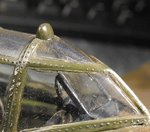
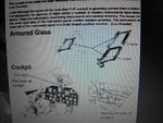
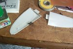
Make it from a piece of clear plastic sheet, about half to one millimetre thick. If you haven't got any, a suitable piece of clear packaging will do, but i'll put a piece in with the other parts.
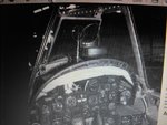
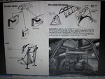
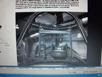
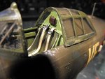
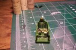
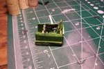
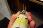
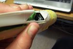
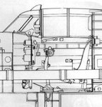
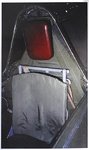
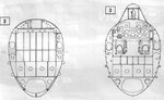
I've just noticed something. The armoured bulkhead with the headrest in the cockpit set is designed for the bubbletop P47 from what I can see. You'll have to adapt this by cutting off the top, level with the kit rear bulkhead, where the canopy goes. Don't do anything until you see the pics/drawings I'll post, and if you can post a shot of it from the side, that will help.
 
Here you go H. I'm having a temporary connection problem with my scanner at the moment, and for some reason the pics I want to print to PDF from a book on the PC are transfering, but not showing! So, quick solution, photograph the screen and a model!
The model is over thirty years old, very dusty, and rather battered! It's the old Revell 1/32nd scale Razorback, which could be a lot better - sort of lost interest and just finished it, with a view to improving sometime. Yeah, right!
The first three pics are shots taken off the PC screen, from Squadron's P47 Walk About. Sorry for the quality.
The next two are the battered old model, showing the bulkhead and head rest, and an external view of the armoured screen, behind the pointed windscreen.
Final pic is a drawing of the screen, again from the Walk Around book.
 

Attachments

  • Can Jan 294.jpg
    Can Jan 294.jpg
    59.6 KB · Views: 137
  • Can Jan 309.jpg
    Can Jan 309.jpg
    75.2 KB · Views: 140
  • Can Jan 310.jpg
    Can Jan 310.jpg
    67.8 KB · Views: 142
  • Can Jan 308.jpg
    Can Jan 308.jpg
    66.3 KB · Views: 126
  • Can Jan 301.jpg
    Can Jan 301.jpg
    52.5 KB · Views: 162
  • Can Jan 297.jpg
    Can Jan 297.jpg
    74.8 KB · Views: 130
Thanks T!

Still confused as to the seat? What do I have to do with the headrest? I have to go out tonight but when I get back I'm probably going to go work with the seat next. Should the screen and gunsight go on after the model is painted and put on before the canopy goes on.
 
Yes, fit the screen and gunsight, then the pointed windscreen (when you get it from me!), preferably after painting - makes masking easier. I need to see a front and side shot of the seat bulkhead and head rest. If the head rest armour is angled forward, then it's for a 'bubbletop', and needs to be cut off, and re-modelled to be 'flat' against the upper fuselage spine, as in the pic I posted. You might need to make a new one from card or plastic card, unless the kit fuselage has one already.
 
Ok first question, when I add the razorback part do I line the panle up with the new arch or do I keep it where it was before?

The the last 2 are your shots.

FItting is gonna be a nightmare I can already tell from the dry fit......
 

Attachments

  • 102_6888.JPG
    102_6888.JPG
    85.2 KB · Views: 123
  • 102_6887.JPG
    102_6887.JPG
    96.9 KB · Views: 148
  • 102_6886.JPG
    102_6886.JPG
    38 KB · Views: 124
  • 102_6885.JPG
    102_6885.JPG
    44.5 KB · Views: 137
OK, first things first. The seat bulkhead appears to be the correct one for a razorback, so that's good. BUT ! It looks like you might have fitted it leaning slightly to the left, when viewed from the front, although it might just be the camera angle/ wide lens making it look like that. Check it, as it'll need to line up perfectly with the leading edge of the rear of the razorback.
Next, if you mean by 'arch' the forward end of the cockpit of the razorback, where it goes over the instrument panel, then yes, line up on there. But you'll need to either hollow out that 'dish', and add frames, or build it up to form the coaming, like in the pics I posted.
Finally, where the rear openings are, in the side of the razorback, immediately behind where the seat and bulkhead go, should have concave 'walls', as you can just about see in the oic of my old model. If the kit doesn't provide parts for these, just fit some card, inside the fuselage, to blank them off, lining up with the seat bulkhead. Now you know why that has to be straight and 'square', otherwise nothing will line up, and the canopy won't fit, open or closed!
Hope this makes sense.
I don't think fitting the razor will be too bad, although you'll probably need some filler along the joints. Just ensure this is smoothly filled and sanded flush, with no lumps or bumps to give away the joint!
 
Alright, so, I'm making framing BEHIND where the rear bulkhead goes.

Wait I understand, the armor has to line up with the fuselage. And to get the panel to line up I need to sand it out and add the framing there. To fit around the panel I suppose?

The where are the rear openings?

My apologies Terry if I'm wasting ur time :oops: :(
 
Here's a couple of things that might help out. hope its not too late, I was out all day. The cutaway is the drawing I used to set up the alignment of my 1:1 cockpit and everything worked out real nice.
 

Attachments

  • Scale cockpit plan.jpg
    Scale cockpit plan.jpg
    46.8 KB · Views: 130
  • P47G_Headrest.jpg
    P47G_Headrest.jpg
    46.4 KB · Views: 137
Thanks Glenn i am still having a hard time figuring out what I do. Do I sand the area that sits above the panel and then what. Also I just have to align the seat? Thanks
 
Harrison I have a look thru my pictures and see what I have for a razor back dash. Most of my stuff id for the bubbletop but I know I have some stuff for yours there too. Be back in a few
 
Here's all I have Harrison I'm not really clear on what problem you're having but I hope these will help.
 

Attachments

  • p47_cockpit.jpg
    p47_cockpit.jpg
    73.5 KB · Views: 122
  • Tbolt01.jpg
    Tbolt01.jpg
    132.9 KB · Views: 142
  • TBolt02.jpg
    TBolt02.jpg
    98.9 KB · Views: 116
  • P47G_Instruments.jpg
    P47G_Instruments.jpg
    78 KB · Views: 118
  • scale cocpit section.jpg
    scale cocpit section.jpg
    56.8 KB · Views: 127
  • Image-30.jpg
    Image-30.jpg
    172.1 KB · Views: 130
  • Image-31.jpg
    Image-31.jpg
    156.8 KB · Views: 119
Ok so today what I decided to do was figure out the issue of the machine guns. I was thinking of doing stretched spure BUT our kitchen is still getting worked on and I don't have many other places so what I decided to do was some searching.

What a better place to get .50s than a half built....fully butchered B-17?

So I took all the guns from there and drilled out the barrels with my pin vice, found the postitions of a gun on a P-47 and added them. if there are only 3 guns on this model I can sand one of the .50s down to plug the hole which will be very helpful.

PIC 1: My new gun barrels....

PIC 2: Testors excuse for a gun barrel.
 

Attachments

  • 102_6893.JPG
    102_6893.JPG
    77.6 KB · Views: 127
  • 102_6894.JPG
    102_6894.JPG
    84.1 KB · Views: 130
Harrison, The guns of the P-47 angle downward in relationship to the wings, and to a lessor extent to the fuselage due to the attitude of the aircraft in flight. You can compare the guns in the first photo to the panel lines on the fuselage and see how much they angle downward. Also in the second picture the blast tubes of the guns exit the wing slightly above the centerline of the wing. and not quite parallel to the centerline with the inboard gun slightly higher than the outboard gun.

If you plan to do some detailing in the landing gear or wheel wells let me know as I have some detail shots that could help, and get them to you before you actually start on it
 

Attachments

  • 3020380687_76097738fb_o.jpg
    3020380687_76097738fb_o.jpg
    104.1 KB · Views: 118
  • 3021205368_b38d747040_o.jpg
    3021205368_b38d747040_o.jpg
    104 KB · Views: 110
Thanks a bunch Glenn! Will go fix that

YEs, I just couldn't finish it. No worries, there is another 1/48 B-17 in the stash.

Glenn, if you could post those pictures of the bays it will help a bunch!
 
First Harrison, remember the guns did not have the perforated cooling jackets, as on the free-mounted B17 Brownings. The barrels were inserted into stainless steel blast tubes, as shown in Glenn's pic.
Second, I don't know which gun sights you have, but it will NOT be the K14 computing sight, as this did not reach the first units (with P51D's) until early August 1944, in general, and later to P47 units. For the period of your model, it should be the MkII (equivalent) reflector sight.
Here's another pic of the blast tubes, and a couple to be going on with of the landing gear etc.
Send me an e-mail if you're stuck on the other parts we talked about, with as much detail as possible. I'll reply with the solution, and sketches where needed.
 

Attachments

  • Czech 202.jpg
    Czech 202.jpg
    68.3 KB · Views: 103
  • Czech 203.jpg
    Czech 203.jpg
    83.3 KB · Views: 115
  • Czech 198.jpg
    Czech 198.jpg
    86.5 KB · Views: 129
  • Czech 199.jpg
    Czech 199.jpg
    58.3 KB · Views: 108
  • Czech 200.jpg
    Czech 200.jpg
    91.8 KB · Views: 120
  • Czech 210.jpg
    Czech 210.jpg
    73.6 KB · Views: 137

Users who are viewing this thread

Back