Testors 1/48 P-47D-5 Thunderbolt

Ad: This forum contains affiliate links to products on Amazon and eBay. More information in Terms and rules
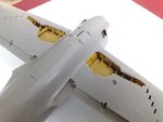
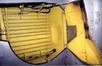
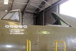
Ask and you shall recieve.:) Hope they are of some use.:D

IMG_6071 resized 25.jpg


IMG_6078 resized 25.jpg


IMG_6061 resized 25.jpg


IMG_6060 resized 25.jpg


IMG_6059 resized 25.jpg


IMG_6058 resized 25.jpg


IMG_6063 resized 25.jpg
 
They are open, there is no walls sectioning them off from the wing.

I see . Here two shots I have grabbed somewhere in the net.If you don't use any rasin bays you will have to scratch-build them. Or you can leave them just as these are.It's up to you only which way you will choose.
 

Attachments

  • P47 model wheel bay.JPG
    P47 model wheel bay.JPG
    50.5 KB · Views: 80
  • P47 wheel bay.JPG
    P47 wheel bay.JPG
    62 KB · Views: 88
Last edited:
Thanks very much Wojtek. That's exactly what I was going to draw!
Harrison, even if you don't detail the wheel bays, they'd be much better at least 'boxed in' with plastic card walls. After all the resin parts and time and effort spent on the model, a little extra work won't harm, and it'll make all the difference. I'll get the parts in the post to you tomorrow, so with a bit of luck, you might have them in about 5 to 7 days. (That's if someone tells Royal Mail that's how long it should take, max !)
 
Thanks Terry! Appreciate it. I am going to start on the wells later this week.

Here Terry. The second 'blank off' attempt needs to be redone me thinks to get the same angle etc. etc.
 

Attachments

  • 102_6904.JPG
    102_6904.JPG
    61.5 KB · Views: 109
  • 102_6905.JPG
    102_6905.JPG
    57.6 KB · Views: 91
  • 102_6906.JPG
    102_6906.JPG
    52.8 KB · Views: 89
Last edited:
See what you mean! The warped spine doesn't help either. It might be easier to fit the card inside the razorback, with a 'lip' all around. When this is totally set, it can then be filled and smoothed and sanded to the contours of the razorback spine. Also, just check that the front of the razorback, where the headrest goes, will be vertical when fitted to the fuselage. It needs to be, to line up with the bulkhead/head rest.
 
Ok, so shall I remove them both?

I was looking at the spine and i'm thinking, is it because one of the traingles was too big? Warped, should I fix it or leave it.

Its hard to test fit since I have to put fuselage halves together.
 
It could make it worse trying to straighten it, due to the realtively low curve. Take out both pieces of card, and put some inside, as mentioned, filling later, when set. Make sure the front of each piece of card is vertical to the cockpit rim. You might have to dry fit the fuselage and spine to check this, as you'll need to see where the card actually sits.
It might be an idea to use each side of the spine as a pattern, and trace the shape of the triangular cut-outs onto paper, then transfer this tom the card, allowing an overlap on the inside, so that it can be glued. thsi will also help to achieve the vertical line of each piece of card.
Hope this makes sense. And now, I'm off to try to do a bit on the MiG, then bed!
 
Ok thanks T! Looking forward to the MIG update.

So for this week(s) :lol: we have:

Make a more circular pattern for the instrument panel

Making the wheel well sectioned off

And adding the triangles to the spine

**DEEP BREATHS** :lol:
 
Harrison this might help with the canopy opening in the razorback. It looks like the blocked out area does not come all the way forward, and also is recessed back from the fuselage surface. It may be relativity simple to glue some card in from the inside and let the thickness of the fuselage plastic be the depth of the recess, if you follow what I'm saying. That way the shape of the plastic you filled in with wouldn't be that critical as it would be cut over size and all edges of it except the front one would not be visible. If this doesn't make sense I'll draw you a picture. It should be a simple fix.
 

Attachments

  • p-47d20.jpg
    p-47d20.jpg
    92.5 KB · Views: 91
Thanks so much everyone for all the help I'm getting :oops:

Glenn, do you mean, cut the card and glue it further back since the area I originally had the card on didn't come out all the waY?
 
Here's a sketch I did that I hope will clear things up.. The card should cut oversize and glued to the inside surface of the fuselage. After the fuselage halves are joined the 2 pieces of card should be joined with another triangle shaped piece parallel and in back of the armor plate. Use this drawing with the photo from my last post
 

Attachments

  • ScannedImage.jpg
    ScannedImage.jpg
    43.9 KB · Views: 98
Last edited:
Hard concept to understand using just words!! Make sure you clean up the glue from the last attempt before you do this because the edges you glued the card to previously will be visible. Good luck!
 
Thanks and will do.

I have a science final tomorrow then Spanish (My strongest subject, NOT!)

THEN im home free
 

Users who are viewing this thread

Back