Damn Terry. Love your bulkhead work!
Navigation
Install the app
How to install the app on iOS
Follow along with the video below to see how to install our site as a web app on your home screen.
Note: This feature may not be available in some browsers.
More options
You are using an out of date browser. It may not display this or other websites correctly.
You should upgrade or use an alternative browser.
You should upgrade or use an alternative browser.
1/48th Mitchell II - Allied Advance and Defense of the Reich WWII.
- Thread starter Airframes
- Start date
Ad: This forum contains affiliate links to products on Amazon and eBay. More information in Terms and rules
More options
Who Replied?T Bolt
Colonel
Too bad a lot of that detail will be destrorted behind the thick canopy. Does True Detais make a replacement? Or if not could you plunge form a new one from the old one?
- Thread starter
- #163
Airframes
Benevolens Magister
Thanks again chaps, it's much appreciated.
Glenn, there is a vac-form canopy available from Falcon / Squadron, and yes, I could mould a new one. But I'd have the same problem I'd have if I used the beautifully clear, and thin, spare canopy from the B-25J kit - fit around the lower sills (and overall depth with the 'J' canopy). The same with the nose transparency, where again the 'J' part is much better (and in two parts, making it easier to mount the gun and align it with the flexible ammo feed chute).
The Mitchell had very smooth lines, and I want to blend the edges of the canopy into the fuselage, to make it look part of the aircraft, rather than show a distinctive lip, or joint line, an area which has spoiled the overall finish of some models I've seen.
To this end, I've already filed a 'trench' into the extreme forward end of the instrument panel coaming, where the windshield sits, and I've also thinned-down the base of the windshield and the canopy edges. Once fitted, the joints will be concealed with either PVA or 'Milliput', and blended smoothly into the fuselage.
I think that, once the transparencies have been polished, and had a dip in Humbrol 'Clear', they should look a lot better.
So, on to the small amount of progress made today.
Before starting to add the interior detail, some work had to be done on the tail gun position, and the waist windows, as some internal painting was required on both areas before proceeding further.
PIC 1. The inside areas of the aperture cut in the tail planes was painted in the interior colour (more on that later in the build), and then the pre-masked, cut-down canopy was fitted, on top of some strips of plastic. These are being used to raise the canopy at the rear end, and to bring the windshield nearer to the vertical, as this was not as 'sloped' as the one on the later 'J' model.
A half bulkhead was also made and attached to the rear of the canopy part, and painted on the inside.
PIC 2. The nose section of the drop tank, being used to form the basis of the cupola fairing, was also mounted onto plastic sheet, again to raise the part slightly, and then glued into place. Once fully set, the shape and profile of the 'solid' part of the cupola will be built-up using 'Milliput', blended into the rear edge of the transparent part, and then sanded to final shape.
PICS 3 and 4. As the waist windows need to be fitted at this stage, in order to mount the breech end of the guns (the barrels will be removed, and the resin barrels added after painting the model), the inside of the window apertures were painted, the windows masked, and then thin plastic card was cemented onto the top and bottom edges. When set, these were trimmed, and sanded to shape, to form the curve of the 'bay window' frames.
PIC 5. The assemblies were then fitted to the apertures, resting on the rebated sills fitted earlier, and liquid cement was applied around the edges and on the edges of the plastic additions.
Once these have fully set, the bulged fairings top and bottom will be formed using 'Milliput'.
That's it for now, but all being well, and barring interruptions, I hope to get most, if not all, of the interior done over the weekend.
Thanks once again for your continued interest, and compliments, and I'll post further up-dates over the next couple of days.
Donivanp
Lieutenant Colonel


Wildcat
Major
Great work Terry!
- Thread starter
- #167
Airframes
Benevolens Magister
Thanks chaps !
Still plodding on - might have some progress pics later.
Still plodding on - might have some progress pics later.
Great progress Dogsbody
- Thread starter
- #169
Airframes
Benevolens Magister
Thanks Red Two.
Got a bit more done, although stiff hands and wrists made things a bit difficult, and slowed things down somewhat.
The tail gun cupola has been blended-in with 'Milliput', and the waist window 'blisters' also moulded using 'Milliput', and both areas will be sanded to final shape once the putty has fully set.
A start has been made on adding some internal detail, although due to the stiff hands problem, the work is a bit rough at the moment, and will need some tidying.
PIC 1. Shows the 'Milliput' added to the drop tank section used as a base for the tail cupola, and awaiting sanding to final shape.
PIC 2. The waist window blisters, also moulded using 'Milliput', and again awaiting sanding to final shape.
PIC 3. An extra panel has been added in the nav/radio op's position, and the quilted insulation in the cockpit has been simulated by gluing strips of embossed foil onto the sidewalls, the foil being sourced from the packaging on the pain-killers I get on prescription.
Once a couple of switch and instrument consoles have been added, the 'insulation' will be painted in a pale green shade, and given a wash to bring out the 'quilt' detail.
PIC 4. The first stage of detailing the nav/radio op's station has been done, with the antenna tuning unit (top left) looking rather askew, and in need of correction. (I couldn't get my hand to release the tweezers when placing the parts, resulting in the top and bottom sections coming adrift ! It will be corrected tomorrow, when my hands are, I hope, more responsive !!).
Below this is the main electrical panel, awaiting some basic detail, with the jump seat and back rest cushions alongside and, on the lower bulkhead, the beginnings of a fire extinguisher, which has yet to have the pumping handle and retaining bracket added. British fire extinguishers of the period were often a pre-filled 'bottle' of extinguishing medium, probably protein foam (real smelly stuff, made from pig **** !). which were operated by pumping a handle, in a similar fashion to using a bicycle tyre inflator. Contrary to popular belief, they were not normally painted red, but were a polished, brass finish. (the red colour, and the colour codes for various other types of extinguisher, was a post-war practice, although American versions, and some later, 'ground -based' British water-filled examples, could be seen in red).
PIC 5. The entrance well bulkhead has had the landing gear emergency hand pump assembly made and added, with, to the right, the main hydraulic and brake system accumulator cylinders.
To avoid damage to the internal fittings, the waist window blisters will first be sanded to shape, before commencing further work on internal detail. Radios, sourced from the spares box, will be fitted to the nav compartment, and other items such as the 'Gee' receiver and its R/F unit, will be scratch-built and fitted on the port side of the compartment, together with some representative wiring etc.
The rear fuselage will have a couple of jump seats added, as well as the dinghy container, ammo boxes and feeds for the waist guns, the gun receivers (resin barrels to be added after painting the finished model) and their counter-weight pulleys will be fitted at this stage, and the dorsal turret pedestal , folding bicycle-type seat and ammo boxes will be scratch-built and fitted to the floor. The turret itself, which will again be fitted after painting the model, needs to be 'opened up', as it's basically a solid, flat disc with a raised 'lump' on to which the kit guns are mounted. The 'disc' will be cut open, and a gun sight and ammo feeds added, with the gun breeches again being sourced from the spares box, with resin barrels.
I was hoping to get all of this done over the weekend, but my stiff hands are making work rather slow, so it'll probably take a few days to complete all of this.
More pics and progress report when there's more to show.
Donivanp
Lieutenant Colonel
Great looking work here Terry. Simply great.
Wildcat
Major
Awesome work Terry!
- Thread starter
- #174
Airframes
Benevolens Magister
Thanks very much chaps !
I'm in the process of sanding the tail cupola and waist window blisters, and hope to continue with some more interior fittings later today.
More pics soon.
I'm in the process of sanding the tail cupola and waist window blisters, and hope to continue with some more interior fittings later today.
More pics soon.
Great work so far Terry!
Looking good T-Bone!
- Thread starter
- #177
Airframes
Benevolens Magister
Thanks very much, Hugh and Jim.
I've spent around five hours working on the model, but don't seem to have much to show for it. Most of the time was taken up with sanding the tail cupola and waist window blisters, with a diversion to apply the basic colour to the interior, and work out exactly where the radios and other equipment will be fitted.
But, now that the interior is painted, it shouldn't take too long to make and fit the rest of the detail parts (he said, hopefully!).
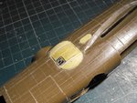
PIC 1. The waist window blisters were carefully shaved and sanded to shape, finishing with 1200 grit to polish, and were then given a coat of primer to check for blemishes. The small oval windows, filled with 'Milliput', were also sanded, rivet lines added, and coated in primer.
Unfortunately, I forgot to photograph the primer stage before the camera batteries died, but a visual inspection showed that a very small amount of extra sanding is required here and there, just to improve the blend of the blisters into the fuselage.
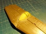
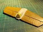
PICS 2 and 3. The 'Milliput' area on the tail cupola was carved, shaved and sanded to shape, again finishing with 1200 grit, and primer applied to check the overall finish, and the merging into the tail plane section.
Again, there is a very slight blemish on the port side, but as this is at the line where the 'solid' section meets the frame of the glazing, I'm not too concerned, and I'll accept it as it is, rather than possibly make things worse by attempting to improve the area. Also, once the darker Olive Drab (faded and patchy) is applied, I doubt the blemish will be visible to the naked eye.
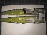
PIC 4. The interior has been painted in the base colour, and will be dry-brushed with a slightly lighter shade, and given a slightly darker wash, to highlight the frame details.
Although it looks very green and bright in the photo, the colour is actually a mix of Khaki Green and yellow, in a satin finish, very slightly darker than the standard Interior Green, and is, to an extent, a compromise. Depending on the production factory, and the Block number (early v late production), the B-25 was finished internally either in Interior Green, Bronze Green, or a shade in between. As with the 'J' model, these late 'D' models, produced at the Kansas facility, were more likely to be in the Bronze Green, with interior fittings, brackets, seats and seat frames in Interior Green. Areas not occupied by the crew, such as the entrance hatch outer wells, were often in yellow zinc chromate, the primer colour used on the overall airframe.
As visibility (into the interior) is already somewhat restricted due to the minimal glazing, which as already mentioned is rather thick, and distorts the view, I thought that the fairly dark Bronze Green, or even the hybrid 'intermediate' colour, would be too dark, absorbing what little light entered the interior, and thereby hiding any detail which could be seen. I therefore opted for the mix used, which gives an impression of being darker, without actually masking the detail.
Items such as the seats, seat frames, and some selected areas of the bulkhead etc, will be painted in the slightly lighter Interior Green, which should hopefully allow some contrast, an emphasise the detail slightly.
Note that there are still some 'bare' areas, left free of paint, where equipment will be cemented in place.
PIC 5. RAF Mitchells were fitted with British radio and navigation equipment (as well as Sutton seat harnesses in the cockpit), and the first to be fitted to the model, the radio transmitter and receiver, were 'borrowed' from the Airfix Mosquito FB.VI kit, which, when built, will have the later, American SCR VHF radios fitted (I might enter the Mossie in this GB if I get the Mitchell finished in good time).
These have had the base colour applied, plus mounting frames made from plastic strip, and await detail painting. Rather nice moulded detail (especially considering this kit dates back to 1979), which should look good when picked out in the various colours.
Once painted, these will be mounted on the starboard side of the radio / nav compartment, immediately behind the cockpit, and will be visible through the canopy, and possibly the side windows (which will be moulded from clear sheet, to replicate the bulged version on the real aircraft).
Next step is to scratch-build the 'Gee' monitor and its associated R/F unit, and fit this on the starboard side of the compartment, then paint the other details such as the seat and other equipment 'boxes', before turning attention to the rear compartment, and adding the gunner's transit seats, ammo boxes etc etc.
Thanks again for your continued interest, and I'll post more soon.
Attachments
Looks good
- Thread starter
- #179
Airframes
Benevolens Magister
Thanks mate !
Crimea_River
Marshal
Good work Terry. The kind of stuff you're doing does take a long time with minimal apparent progress but you're doing well.
Users who are viewing this thread
Total: 1 (members: 0, guests: 1)

