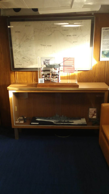
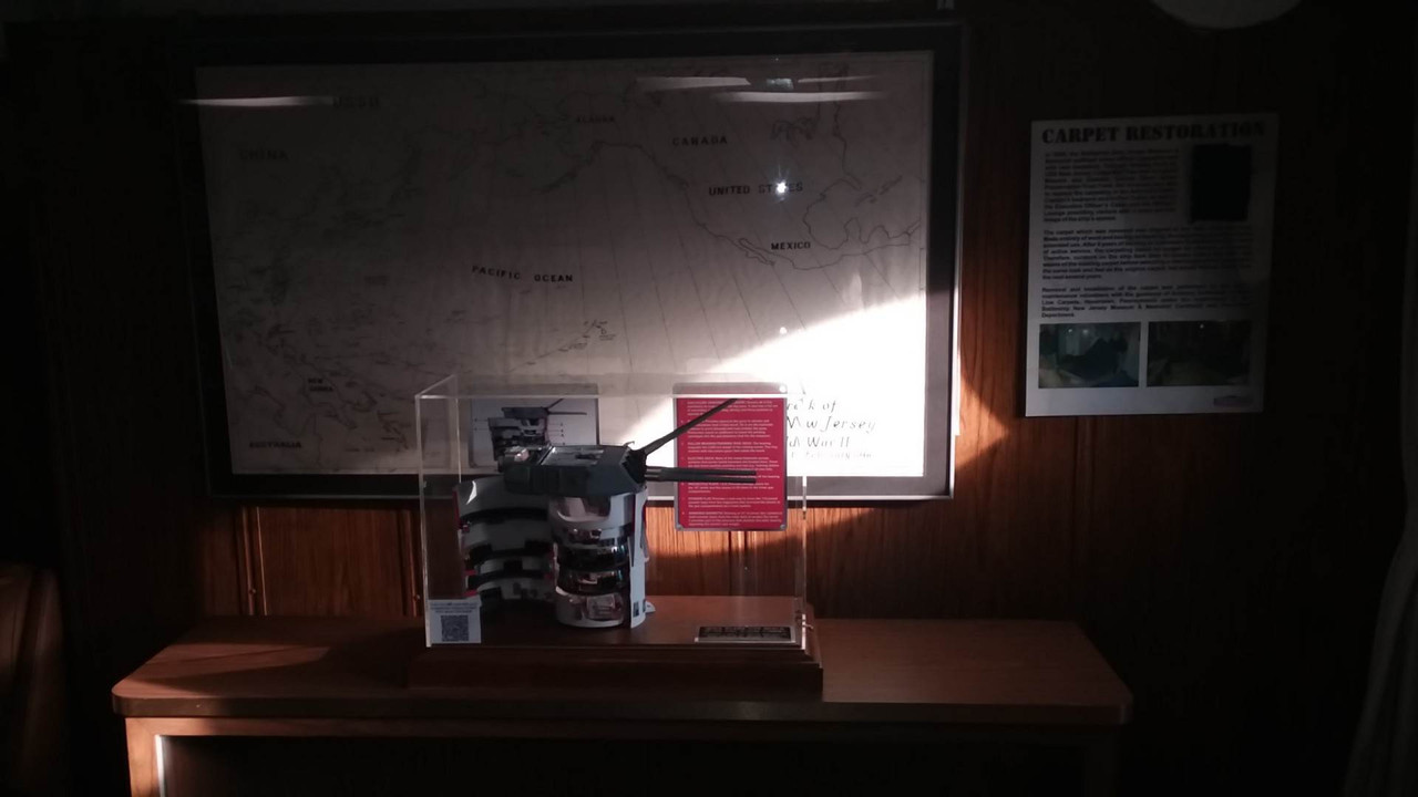
1:72 Complete Iowa Battleship 16"-50 cal Turret with interior down to the magazine

Ad: This forum contains affiliate links to products on Amazon and eBay. More information in Terms and rules

First of all, thank you. I'm 77 going on 78 so age has doesn't have much do with it. Most of the motorized tools have been aquired in the last decade from Harbor Freight. They're all Chinese and really cheap. They don't last long, but a) my usage is very light, and b) not sure how long I will last.

All the rest of the stuff has been collected for years. My most expensive single tools are my Taig lathe and accessories and my American Beauty Resistance Soldering Unit.

What I lack in skill and artistry, I compensate with tenacity. I really don't like to give up and will keep going at it until it gives up. I never break stuff intentionally, and never ever throw tools, parts or models. If it isn't working, I'll walk away and let my subconscious figure it out. I trust the force and it usually delivers. And I'm never afraid to get help from others. I enjoy helping others and like to get help.

Jim Slade, the fellow who sent me those superb 3D drawings, just bought a 3D resin printer and needs a lot of help getting started. I'm giving that help. Give and take… makes the hobby great!
 
The model's in its "almost" final position. The ship is closed to the public until March, but they were having a board meeting and Ryan wanted them to see it. It is now on temproary display in the ward room. It's sitting on an end table between two couches and it's not a secure place. It's eventually going onto the bookcase in the background... a much better location.

The board members were not told that I was building this model and were duly impressed.

ITP-On-Display-in-Big-J-1.jpg


ITP-on-Display-on-Big-J-2.jpg


Ryan's also going to see if he can get some higher resolution images for me.

Now you're all up to date.
 
Thanks all! The question hanging out there is whether or not the other museum ships with 16" gun turrets would be wanting one too? There are three other Iowa class ships, plus the USS Alabama in Mobile, the North Carolina in Wilimington, NC and the USS Texas in San Jacinto National Monument, TX. It would take me about 1/2 the time to make another and I could theoretically build more than one at a time. I pretty much know where all the gremlins are and have most of the printing files optimized so my scrap rate would be greatly reduced. I would love to make the outer shells out of brass instead of styrene for a whole bunch of reasons. Out of pocket costs are in excess of $600.00, and labor would be about 150 hours going forward. I'm thinking about $5,000 plus shipping per model. I could drive it to the North Carolina and the Wisconsin, but the others would have to be shipped.
 
Absolutely amazing project, I'm in awe at the dedication, commitment and skill involved in seeing it through. Equally impressive is just the level of complexity and amount of equipment in each of those turrets. I had a chance to crawl into a small part of a turret on the USS Alabama in Mobile. For such a large assembly the interior space for the sailors is tiny and incredibly cramped! What further impresses me is all of the original design, fabrication and machining was done with 1930s-40s technology. No CAD design, all on the drafting board. No finite element analysis, all slide rules. No CNC machining or computer-drive burn tables. Would love to see how all those components were fabricated back in the day, particularly the massive roller bearings and ring gears of the turret ring. IIRC somewhere around 150 sailors were required to man each turret and magazine. Perhaps equally impressive-the sailors were (by my boomer standard) kids, all with limited enlistments for the most part, and all trained and capable of operating such a complex piece of equipment. Had to be a real performance when putting steel on target at a high rate of fire. Also would really like to understand more about just how the mechanical fire control computers actually worked.
 
Absolutely amazing project, I'm in awe at the dedication, commitment and skill involved in seeing it through. Equally impressive is just the level of complexity and amount of equipment in each of those turrets. I had a chance to crawl into a small part of a turret on the USS Alabama in Mobile. For such a large assembly the interior space for the sailors is tiny and incredibly cramped! What further impresses me is all of the original design, fabrication and machining was done with 1930s-40s technology. No CAD design, all on the drafting board. No finite element analysis, all slide rules. No CNC machining or computer-drive burn tables. Would love to see how all those components were fabricated back in the day, particularly the massive roller bearings and ring gears of the turret ring. IIRC somewhere around 150 sailors were required to man each turret and magazine. Perhaps equally impressive-the sailors were (by my boomer standard) kids, all with limited enlistments for the most part, and all trained and capable of operating such a complex piece of equipment. Had to be a real performance when putting steel on target at a high rate of fire. Also would really like to understand more about just how the mechanical fire control computers actually worked.
Thanks for the lovely and thorough response! The turrets were manned by 88 sailors. The was one officer-level person in the gun house and one communications ofc of lower rank. When Ryan Syzmanski examined the roller bearings they were still perfect after 80 years. To his knowledge they were never replaced. I too am in awe of the 1930s/40s tech on display. Just the special lathes that were developed in the late 1800s to cut the step-thread Weilan breaches are amazing. To do so on a model is almost inconceivable.
 
Thanks for the lovely and thorough response! The turrets were manned by 88 sailors. The was one officer-level person in the gun house and one communications ofc of lower rank. When Ryan Syzmanski examined the roller bearings they were still perfect after 80 years. To his knowledge they were never replaced. I too am in awe of the 1930s/40s tech on display. Just the special lathes that were developed in the late 1800s to cut the step-thread Weilan breaches are amazing. To do so on a model is almost inconceivable.
I has to look up the Weilan breach. I'd seen pictures, but never realized that the threads were stepped, rather than being a simple 1/3 segment interrupted thread. Amazing design, and after seeing it, I can't envision how the heck it was machined, especially at that time frame. Now I have something else to spend time researching.

Concerning the 16"/50 caliber Iowa fire control system, I had read a little about them some time ago-needed to go back into it again. Pretty decent wikipedia article. Armament of the Iowa-class battleship - Wikipedia It doesn't get into the mechanics of the mechanical computers, but does at least cover the various systems and inputs used to calculate aim points and control of the turret/guns.

I've always been interesting in the manufacturing aspects of products in general, and firearms/weapons/aircraft in particular. Even back to the original Colt revolvers or Winchester lever actions, the machining processes, given the tools of the day, were amazingly advanced. Going into WWII, the fabrication/construction of ships and planes and what was done with the technology of the era amazes me. (same can be said all the way back to pre-WWI battleships). Looking at say a radial aircraft engine, the complexity and compactness of the design, the drive of the cams and actuation of the valves, and everything else involved, being designed on drafting boards and built with manual machines is impressive. Smart guys in those days. Programming and operating a CNC or wire EDM, or designing in Solidworks is pretty simple in comparison! Gotta say, modeling that turret you built in Solidworks would be a fun challenge-but frankly I'm not that committed! At one point I had thought about looking into tank design details and modeling some.
 
The Weilen lathes had a cam arrangement that kicked the cross slide back out of the cut as it reached the end of the segment. I'm sure a CNC could do it today without too much trouble. They were ingenious!

Regarding doing the drawings and calculations by hand… there is no doubt that computer drawing and design has reduced the drudgery and time, but not the mental effort. It just lets you make mistakes faster.

That said, I have a gear drawing extension on SketchUp that draws involute gears by just inputting pitch circle diameter and number of teeth. To draw the large internal ring gear, I first drew it as an external pinion and then used that planar profile as a "cutter" to inscribe the gear's shape in reverse inside the ring. I used PUSH-PULL to extrude the gear's 3D shape. The extension can not draw ring gears so you have to finesse them. Forget about drawing one by hand. It's a non-starter.

All kinds of very sophisticated high tech had to be available to a "normal" hobbyist like me in order to pull off a model like this. I've made a list and it's long. "Normal" is in quotes since my wife may disagree with that description. The word "obsessed" is often thrown about.
An update:

The model is now in its final location and it's much better. My wife and I plan on visiting the ship in Mid-April. I haven't received any feedback on its reception yet.

338530271-128491546846802-7186206077798233446-n.jpg


338694784-998118361569022-249388618501695741-n.jpg


To refresh everyone's memory, this is in the ward room on the main deck of the USS New Jersey.
 
A fitting location for a very worthy exhibit. I should hope that the reception will be swift and appreciative!
 

Users who are viewing this thread

Back