5" 38 Mark 28 Twin Gun Secondary Battery from Iowa Class Battleships

Ad: This forum contains affiliate links to products on Amazon and eBay. More information in Terms and rules

That's kind of poetic isn't it.

Last Wednesday was my wife's 3rd of 4 chemo infusions. With the revised dosage, things are considerably better than the first session, but chemo is still awful. By attacking all cells in your body that replicate more frequently, it affects all mucous membranes, the linings of your entire alimentary canal, taste buds, lining of the mouth, and of course hair follicles. But with all that, she's doing pretty well and the end is in sight.

My sister sent me an article in the Philadelphia Inquirer that described and entirely new vaccine approach to enable people with the BRCA 2 genetic mutation to effectively fight nascent cancer cells. BRCA mutations do not cause cancer. They eliminate one of the body's natural defenses to kill them when they're going rogue. This vaccine, now in human testing, injects DNA into the white cells that identify cells that are cheating by extending their telomeres at the end of the gene, thereby granting the cell immortality, when it should have died. It's one of the cancer cells tricks to do what it does. It's a novel approach that offers great promise.

All of this medical stuff has reduced my model building. That said, I'm still doing something.

Today, that something was to glue the gun house together, sand and then fill all of the gaps and discontinuities, secure the wiring harness, and get it ready for painting. Too bad I wasn't further along because today was a wonderful day to paint outside… 72 degrees, sunny and fairly calm breeze. Alas, the paint will still have to wait until the GH is fully prepped.

Gluing was a delicate operation. I had to avoid clamping too hard and keep away from the ladder rungs and the gun sight on the roof. As it is I did whack a couple more rungs. No big deal. I just drill them out and replace them. I guess I should have waited until all the sanding and filling was done… 20/20 hindsight. *"If my foresight was as good as my hindsight, I'd be better by a darn
sight!"*


5IP GH Glued Up.jpg


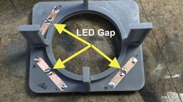
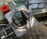
After the glue up was secure and I sanded the joints to level them, I secured the LED wiring inside. I'm running the three LEDs in series so one set of red and black leads will be tied together, It was too cramped and awkward to attempt the splice inside the gun house. Instead, I'm running all four leads out, splicing them and then running them into the upper handling room. Again, I used Bondic as liquid cable clamps.

5IP GH Wiring.jpg


I was then able to apply some Bondic to close any larger gaps and finish up with Tamiya Fine Putty. After curing overnight I'll do the finish sanding, fix any broken rungs and get it primed. Don't know what tomorrow's weather portends yet. I'll have to check.

5IP GH Filled.jpg


I also have some bolt heads to add to the sides to line up with the framing members that lie underneath. I added these on the print, but the sides are sheet styrene. In retrospect I could have printed all of the gun house flat surfaces considering how well the upper handling room walls came out.

Speaking of the UHR, I glued three of the four walls together with thin CA and accelerator. All along I've been assuming that I'll just leave off the front wall, but I rethinking that. I may want to install it and then cutaway some for viewing.
 
Nice to know your wife is managing in her own way and with the end in sight the spirits is usually lifted. As for your project, your going great guns (no pun intended) when you consider the other stuff going on in your daily life. :thumbright: :D
 
Thanks for the lovely thoughts. Being retired an a semi-professional model maker, beisdes caring for my wife, it's really what I do.

Today, I'm still working to get the gun house ready for paint. I did decide to build all four walls of the Upper Handling Room and then cut away viewing areas. I came to this conclusion since it makes it look more finished, and adds structural integrity.

I had to fix an addional bunch of ladder rungs. Boy! Lessons learned: put the darn rungs on at the end just before you're going to paint. Now if only I had to make another one of these to apply this brilliance… Even with the Tenacious added into my resin mix, these fine parts are still pretty brittle.

I also added the missing bolt heads. I was able to include them in the 3D print for the rear wall, but the styrene side walls needed Tichy model bolt heads. These are styrene so they glue nicely to the styrene walls, but the only ones I had were with a screw projecting out of the nut. After the glue dried I filed/sanded them flush so they looked like my printed ones. That said, I was not particularly impressed with my precision in putting them in. I hope people don't notice. And I broke another two 0.020" carbide drills in the process. I bought resharpend ones this time to save money. I'm not so sure it was a good decision. They're breaking even more frequently than normal.

5IP GH Almost ready.jpg


As I noted above, I assembled all four wallls of the UHR. I had to wet sand the top edge to make sure they were all flush. I have a piece of 400 grit wet and dry paper glued to my Rock of Ages granite surface plate that I use when I want a surface really flat. I drew the cutaway profile with a Sharpie and cut it out with the Dremel and carbide router. I final sanded it with the same Dremel with a sanding drum. Sanding cured resin is nice, unlike styrene with melts almost immediately. It's a thermoset plastic and does not melt with heat applied.
5IP UHR Cutaway.jpg


I also noted on the upper frame piece where the UHR lighting is going since that is up next.

I've put a request into Ryan to take some pictures of the communications and controls that flank the gun captain's position at gun house rear. That detail is the last thing needed to be drawn and printed for the upper works. I'm still wrestling with the below decks stuff.
 
I filled and sanded the UHR walls. I then clamped the floor in place and glued it with thin CA, run as a bead on the inside on a surface pre-treated with accelerator. My work table is a piece that I bought from IKEA in Venlo, the Netherlands, when we lived in Düsseldorf, Germany in 1999 to 2002. I put on a cork tile surface. On top of that is a piece of Corian that is the sink space slug removed from the counter top in our current home. Corian is a great work surface. It's dead flat, smooth, and impervious to every solvent we use. I normally then cover it with a cutting matt, but when I want to align something for gluing I work directly on the Corian… like I did today when I wanted the bottom to be fully flush with all four sides before gluing.

5IP UHR Floor Clamp Bottom.jpg


5IP UHR Floor Clamp.jpg


5IP UHR Floor Glued.jpg

I also final fit the roof and ring support. It needed some triming for clearance of one of the legs so it would center properly. I marked the position for the lighting and installed them via the copper tape method. One girder was a little long and needed some light sanding.

Lighting Install:

This image shows the tape arrangement with the gaps cut for the SMLEDs. The distance from the anode and cathode terminals is just about a millimeter so you can have to very precise in setting the LED in place for soldering.

I test the LEDs before soldering, after soldering each LED and then ther entire circuit. This was the circuit test. After the test I put some Tamiya masking tape tabs on each in prep for paint.
5IP UHR LED test.jpg


I put the lid on the box and looked at the light produced. Un-painted, the light leaks through the semi-translucent resin walls. There will be two coats of paint on inside and outside: white primer and gloss white inside and gray primer and haze gray on the outside. I don't think the light will leak then.

This is another series circuit with three LEDs so the +/- string daisy chains to the starting point. I will combine all the black leads back to the circuit board, and all the red leads will have their own CL2N3 on the board to drive them. That cuts down the absolute number of leads that has to go below. The entire circuit is operating at 20 milliamps so current loading is not a problem. I could have run the entire circut with copper tape, but the opennings through each girder would meant the tape be folded to get through and I wasn't going to attempt that.

5IP UHR Lights On.jpg


To comlete the gun house for paint I decided to put the open doors back on. This time with wire reinforcement. I used a very fine, 0.012" carbide. Believe it or not, I didn't break this one at all. I used 0.012 brass wire for the small cartridge discharge door, but it was too flexible. I changed to guitar string of the same gauge for the big door. I used Xuron hard wire cutters for the music wire. I have a 40 year old pair of Channellock long nose pliers with a wire cutter in the handle end to cut hardened wire and it doesn't do anything to them. When I use other cutters like Xuron regular cutters or any Chinese cutters, they get a semi-circular divots in the cutting edges and it ruins them.

5IP Pinning with tiny drill.jpg


5IP Pinning the Broken Door.jpg


This images shows the holes in the wall side. The holes are so small that I can't really see them without the Opti-visor.

5IP Door FIx Holes.jpg


The wired doors are much stronger. I also broke and fixed at least three ladder rungs and there's still a few more to do. The problem is every time I grab it or put it down on the bench, I'm hitting them. I may reprint more and not post-harden them quite so much so they aren't quite so britte.

I wanted to test fit the GH on the frame and got some surprises. First I had to measure and cut off the telescope ends so I could slip the GH down over the lower part. I test fit the cutoff ends into the blisters on the GH side and they were too long and needed a little more trim to bring them flush with the inside wall. This is necessary so when assembled both parts look like they're contiguous.

That wasn't surprising since I could see on my drawings that the telescopes would prevent assembly and that they seemed too long. The surprise came when the frame impinged on the floor mount rib at the bottom. I either had to shorten the ribs or cut relief into the wall. I chose the latter, but this was delicated since I had to hold it while using the router. One slip and I would have been in a world of hurt. Even though I could reprint a new back wall, it was completely attached to the side walls, and filled. I was able to successfully make the cuts. There is a some trimming needed on the front piece where the corner angles are in the way, but that's not as difficult as doing the rear wall.

5IP Rear Wall Relief Cuts.jpg


While a bit dark, you can see the interference. I'm not sure why I didn't detect this during the design phase and draw the reliefs in. It would have been much more precise.

5IP Girder Wall Interface.jpg


I took a picture with the work completed so far perched on the UHR. As I noted, there's still some work that needs to be done. Right now the floor seems to want to sit below the gun house walls. I think it's supposed to fit inside them.

5IP GH Fit Test.jpg


We'll get there.
 

Attachments

  • 5IP UHR Ceiling LED Prep.jpg
    5IP UHR Ceiling LED Prep.jpg
    1 MB · Views: 6
  • 5IP UHR LED test.jpg
    5IP UHR LED test.jpg
    637.6 KB · Views: 7
Thanks guys

Painting is officially underway. Started on Monday when it was almost 80, and no wind so I could get outside to lay down the Tamiya solvent-based primer; white for the insides and gray for the rest. Yesterday after a full day to dry I airbrushed Tamiya gloss white for interior and a mixture of Tamiya of Gloss whilte an Flat Neutral Gray. I still have to paint the outsides with Life Color Haze Gray. After the white dried I started picking out the detials. This work still goes on. I'm reprinting a couple of parts for various reasons, and repaired a print defect on the ring frame/roof part.

Here's the primed parts.

5IP Parts Prime 1.jpg


5IP Parts Prime 3.jpg


I love how the details pop with the primer on. Before painting I had reprinted a bunch of new ladder rungs and fixed all the broken ones.

5IP Parts Prime 2.jpg


The insides are now fully gloss white. Sorry about the terrible staging…I tend not to spend a lot of time on the picture taking.

5IP GH Interior Paint.jpg


I will have to mask all the opennings from the inside to paint the haze gray on the outside. In the handling of the I broke ANOTHER bottom ladder rung. I'm thinking in my excellent 20/20 hindsight that I should have printed the ladder mounting lugs and made them out of bent wire. These things are driving me nuts and I don't like how slopped up the work looks becuase of all the fussing.

5IP Rung Broken Again.jpg


Detail painting started with the frame assembly. It's a work in progress since there's more to do.

5IP Detail Paint Start.jpg


Today, I went back and overcoated all the rods with Dull Coat to seal the alcohol-based paint so I could paint it with Molotow Chrome paint which is also alcohol-based and would dissolve the white. I did the same on a lot of the gray parts that are going to get any metallic finishes.

I started painting the circuit panels for the UHR. These are not glued it. There's a lot of bits that need to be picked out on these parts.

5IP Detail Paint Start 2.jpg


Today I fixed the print defect on the ring frame. I first trimmed the upper edge so a piece of shaped styrene would properly seat. I then put a piece of art paper as a backing held with CA and filled the broken area with Bondic. After sanding flush, and re-trimming the upper edge, I CA'd the rim piece in and finished sanded that. The repair will be undetectable. This rim will be cut away to expose for view the turret ring base and the training rack and pinion.

5IP Ring Frame Repair 1.jpg


5IP Ring Frame Repair 2.jpg


I also did something I should have done a long time ago. I made a resin vat protecter out of a piece of scrap cardboard. I'm using a spring built plate on my 3D printer that really saves time by letting you pop off the spring plate, bend it to remove the parts, clean it and then snap it back on. It's held by a 3M magnetic backing. The problem arises when I try to align it before snapping it back on. Occasionally I loss grip of it just as I'm ready to snap it up and it heads into the resin vat. That's no big deal. The big deal is when it goes in edge first and the edges are pretty thin. And this edge can penetrate the FEP and that is very bad. Now if it falls, it won't do any damage.

3D Print Vat Protector.jpg
 
Thanks guys

Painting is officially underway. Started on Monday when it was almost 80, and no wind so I could get outside to lay down the Tamiya solvent-based primer; white for the insides and gray for the rest. Yesterday after a full day to dry I airbrushed Tamiya gloss white for interior and a mixture of Tamiya of Gloss whilte an Flat Neutral Gray. I still have to paint the outsides with Life Color Haze Gray. After the white dried I started picking out the detials. This work still goes on. I'm reprinting a couple of parts for various reasons, and repaired a print defect on the ring frame/roof part.

Here's the primed parts.

View attachment 767572

View attachment 767573

I love how the details pop with the primer on. Before painting I had reprinted a bunch of new ladder rungs and fixed all the broken ones.

View attachment 767574

The insides are now fully gloss white. Sorry about the terrible staging…I tend not to spend a lot of time on the picture taking.

View attachment 767575

I will have to mask all the opennings from the inside to paint the haze gray on the outside. In the handling of the I broke ANOTHER bottom ladder rung. I'm thinking in my excellent 20/20 hindsight that I should have printed the ladder mounting lugs and made them out of bent wire. These things are driving me nuts and I don't like how slopped up the work looks becuase of all the fussing.

View attachment 767576

Detail painting started with the frame assembly. It's a work in progress since there's more to do.

View attachment 767577

Today, I went back and overcoated all the rods with Dull Coat to seal the alcohol-based paint so I could paint it with Molotow Chrome paint which is also alcohol-based and would dissolve the white. I did the same on a lot of the gray parts that are going to get any metallic finishes.

I started painting the circuit panels for the UHR. These are not glued it. There's a lot of bits that need to be picked out on these parts.

View attachment 767578

Today I fixed the print defect on the ring frame. I first trimmed the upper edge so a piece of shaped styrene would properly seat. I then put a piece of art paper as a backing held with CA and filled the broken area with Bondic. After sanding flush, and re-trimming the upper edge, I CA'd the rim piece in and finished sanded that. The repair will be undetectable. This rim will be cut away to expose for view the turret ring base and the training rack and pinion.

View attachment 767579

View attachment 767580

I also did something I should have done a long time ago. I made a resin vat protecter out of a piece of scrap cardboard. I'm using a spring built plate on my 3D printer that really saves time by letting you pop off the spring plate, bend it to remove the parts, clean it and then snap it back on. It's held by a 3M magnetic backing. The problem arises when I try to align it before snapping it back on. Occasionally I loss grip of it just as I'm ready to snap it up and it heads into the resin vat. That's no big deal. The big deal is when it goes in edge first and the edges are pretty thin. And this edge can penetrate the FEP and that is very bad. Now if it falls, it won't do any damage.

View attachment 767581
That is !#**!#! amazing work.
 
Double bacon sounds really good.

Thanks all!

Short session today. First I want to share a sort of insidious 3D print failure. When I drew the upper dredge hoists for the upper handling room, I did two versions: open and closed storage lid. I drew the open one first and simply rotated the lid to the closed position for the other. That left a void in the part that, during printing, would fill with liquid resin that would not be exposed to UV to harden it. After curing, the lid warped and opened to release liquid resin all over the part.

To correct, I went back the drawing and closed the upper part to make it solid so the lid would be sitting on a closed space, thereby, not having a pocket of uncured resin to deal with. I just downloaded a new version of my slicer. As new versions go, it's got some problems, but it does have a facility to test the object for voids. You can drill holes in the object in the slicer to open voids so the resin would drain, but in this case it was simpler to just redraw the part. I also correctly displayed the lid clamps in the clamped position.

5IP What happens with Voids.jpg


I'm reprinting the corrected part now.

I had to completely disassemble and clean my Badger XF 150 airbrush. While I always shoot solvent through it after each use, occasionally I have to do a deep cleaning. That involves 15 minutes in the ultrasonic and a lot of fussing. Then I painted the white gloss on the undersides of the ring frame.

5IP Ring Frame Ceiling Paint.jpg


With Molotow Chrome paint I picked out the shafts in the sighting complex. I back painted white where necessary. It's almost done. I don't think I'm going to weather any of this, but I could be convinced otherwise.

5IP Detail Paint Progress.jpg


Next session will continue detail painting.
 
Thanks!

Work continued yesterday on detail painting for the parts completed so far. I have to make some adjustments to my colors after re-checking my references. I was going on false memories of what is brass and what is paint. Today, I'm busy drawing the last gun house and UHR details: the communications and controls that are hanging on various places, including four columns that surround the gun captain's position at the rear GH wall. Once I finish and print those I technically can assemble the gun house and upper handling room.

First, after correcting the UHR Dredge Hoist with the closed lid, I solved the leaking resin problem.

5IP Upper Dredge Hoist Reprint.jpg


There are no details to paint on this part. It's just all gray.

I painted the brass on the gun slides, open dredge hoist, projectile and powder hoists that go betweem GH and UHR, and the brass on the lower dredge hoists. I didn't paint enough brass on the guns and too much on the lower hoists. The lids are not brass.

5IP Brass Painting 2.jpg


5IP Brass Painting 1.jpg


I then spent a lot of time masking the interior of GH and UHR. And, of course, I broke not only another foot rung, but beat the heck out of the two open gun house doors. I'm going to print new ones since the hinges are getting pretty munged up and re-gluing over and over is not working. The exterior gets painted WW2 Haze Gray. Current US Navy color is a lighter, more blue shade of gray. I'm doing WW2 configuration.

The problem is each time I turn the gun house to apply tape and apply some pressure I break something. I kind of knew this would happen.


5IP Masks for Exterior Paint.jpg
 
Last edited:

Users who are viewing this thread

Back