Doin' good Geo!
Navigation
Install the app
How to install the app on iOS
Follow along with the video below to see how to install our site as a web app on your home screen.
Note: This feature may not be available in some browsers.
More options
You are using an out of date browser. It may not display this or other websites correctly.
You should upgrade or use an alternative browser.
You should upgrade or use an alternative browser.
**** DONE: 1/48 Spitfire FR.lX - Jet/Recon/Transport GB
- Thread starter fubar57
- Start date
Ad: This forum contains affiliate links to products on Amazon and eBay. More information in Terms and rules
More options
Who Replied?- Thread starter
- #42
fubar57
General
Oh, to be one of those that can sleep. Anyhoo...thanks Terry and Wayne. Tanks are done, with touch-ups to be done, and the next barrage of questions follows.


Not sure what the part I've got circled is called but it's not in the kit. Is it in the Mk.lX? Also not included is the voltage regulator behind the seat. I've seen models of the Mk.lX with it and with out it. Lastly, I've seen pictures and models of the seat harnesses going behind the seat or through a slot in the seat frame and attached inside the fuselage. I'm assuming the latter and will have to open a slot. Having said that, I forgot I had these belts and would the top two be appropriate for this Mark?


Once again, thanks in advance to any advice.
Geo
Not sure what the part I've got circled is called but it's not in the kit. Is it in the Mk.lX? Also not included is the voltage regulator behind the seat. I've seen models of the Mk.lX with it and with out it. Lastly, I've seen pictures and models of the seat harnesses going behind the seat or through a slot in the seat frame and attached inside the fuselage. I'm assuming the latter and will have to open a slot. Having said that, I forgot I had these belts and would the top two be appropriate for this Mark?
Once again, thanks in advance to any advice.
Geo
Airframes
Benevolens Magister
Good stuff Geo, and what's this 'sleep' thing? Haven't had more than a couple of hours at a stretch in the last four or five days!
The part you have circled looks to be from the Tamiya kit, supplied as a separate part for ease of moulding. It's the top of the frame, and the cross brace, immediately behind the rear glazing, and would be visible on all high-backed Spitfires. The part mainly visible is the cross brace, and this can be replicated by a piece of plastic strip, drilled, or even painted to represent the lightening holes.
The harnesses shown appear to be the later version of the Sutton harness, and were fitted to some late production MkIXs and MkXVIs, as well as late production Tempests, and Meteors etc. There's a possibility they might have been fitted to your subject, and to be honest, in this scale, they would pass as acceptable.
On the Spit, the 'tail' strap coming off the 'Y' shoulder straps, passed through a rectangular slot at the base of the head armour, just above the top of the seat, and reached almost to that cross brace. Twin 'Bowden' cables were attached to a metal plate at the end of the tail strap, and passed over the cross brace, and were anchored deep in the upper, rear fuselage, via an inertia lock and pulley system, the release for which was down by the pilot's right thigh, virtually invisible in this scale.
The voltage regulator on this Mk, if fitted, resembled two cans of beans, mounted one on top of the other, transversely across the rear of the head armour, but, as far as I know without checking, these were on the earlier production MkIX, and replaced by a different type of VR, within the fuselage, on later models. Have a quick look at photos of the Squadron's aircraft, or even others of the period, which should indicate whether or not it was mounted.
Hope this helps.
N4521U
Plastic Pirate
You're doing a mahveluss job on this here plane matey.... well done so far. Keep up the good work.
- Thread starter
- #45
fubar57
General
Thanks for the great input Terry and theng yew Bill. Terry, I've been grinding out 0-4 hours sleep a night for nearly 40 years. If I'm lucky, I may get a solid 7-8 hours once a week. Once went three days without and by the time I finally conked out I was starting to hear colors. So I finally figured out how to use the spitfire.ufk.net site and this is what I found out about my bird---
MK290 LFIX CBAF M66 39MU 2-2-44 340S 3-3-44 CAC ops 6-6-44 414S 10-8-44 Damaged in air raid Eindhoven CB 1-1-45 recat E 22-4-45 SOC 7-5-45
Would it not mention conversion to a recon aircraft? Not sure what the CAC stands for.
Geo
MK290 LFIX CBAF M66 39MU 2-2-44 340S 3-3-44 CAC ops 6-6-44 414S 10-8-44 Damaged in air raid Eindhoven CB 1-1-45 recat E 22-4-45 SOC 7-5-45
Would it not mention conversion to a recon aircraft? Not sure what the CAC stands for.
Geo
Tony Hill
Tech Sergeant
Geo.
CAC .. Category AC damage on ops 3.3.44 with 340 Squadron, (CAC..beyond unit capability, would have needed a contractor to come on base to repair or be sent to an MU.)
This aircraft would have gone to MU and been converted to an FR IX there in all likelihood...that helps us a bit if my theory is correct about placement of the controller. No need to mention conversion as it went to 414 Squadron....none that I have yet seen have it mentioned in the abbreviated aircraft history.
OK, close up of controller (note five pin and three pin plugs at right.

Also note in the bottom picture, the aluminium/steel cover that goes over the plugs to stop them coming off (that I still need to build). This is held by the two small body screws that sit either side of the voltage notice.

More to come!
CAC .. Category AC damage on ops 3.3.44 with 340 Squadron, (CAC..beyond unit capability, would have needed a contractor to come on base to repair or be sent to an MU.)
This aircraft would have gone to MU and been converted to an FR IX there in all likelihood...that helps us a bit if my theory is correct about placement of the controller. No need to mention conversion as it went to 414 Squadron....none that I have yet seen have it mentioned in the abbreviated aircraft history.
OK, close up of controller (note five pin and three pin plugs at right.
Also note in the bottom picture, the aluminium/steel cover that goes over the plugs to stop them coming off (that I still need to build). This is held by the two small body screws that sit either side of the voltage notice.
More to come!
Last edited:
Tony Hill
Tech Sergeant
if you remember some of the photos I sent you some years back, scanned from 'Spitfire in Blue', there was an external shot of the port side of the cockpit and wing root, which showed the rivet or bolt heads, on the outer skin, which held the controller in place. This should indicate its position in the cockpit. From what I remember, it may have been closer to the entry hatch, and not where I previously described, above the throttle, which, I'm sure
Ok Terry, I think I know the picture... but the one on page 37 which I think is the one we are talking about, it is of a XI...the controller is in the place of the gun sight...BUT..no matter as it DOES show the four rivets which hold the "wedge plate". That plate is for the gun camera footage counter in a fighter and the Mk IX had it, so it would already be there for an FR IX and the Type 35 could be slipped straight onto it.
That puts the Type 35 above the trim wheel..still a bugger of a place!! It is where I was going to put mine originally. But it fouls your arm on throttle movement at closing and is hard on the wrists..and is hard to reach with the left hand and very inconvenient for the right..
It would have been operated with the right hand I am sure, left hand on stick and turned to the left to line up the shot with the mark on the canopy side and the mark on the trailing edge of the port wing. NOT a very good position at the speed of heat and 300 ft...very bad for spacial orientation.
Lastly and for interest only..the selector theat the FR IX did not have...
Note in this case the wedge plate mounts a couple of thermometers (one for inside temp, one for OAT.)again proving that the wedge was used in PR's routinely.
Last edited:
- Thread starter
- #48
fubar57
General
Outstanding Darryl. According to my close enough for me calculations, the controller is roughly 3.5mm x 2ish x 1.something or other. I would guess the red and green lights would be at the top. And would the aiming marks be visible in 1/48. Thanks so much for your assistance.
Geo
Geo
- Thread starter
- #49
fubar57
General
Ok, I got the wires, I have the mini drills and I have the crazy glue. What I don't have is the proper or probably, the most hassle free way of building sequence as i haven't done this before. If I paint the interior first, I get gluing issues. If I install the wiring first, I have painting issues, mainly, keeping it all neat and tidy. I know most will be invisible once it is all locked up, but for me, the better I do at this stage, the more the confidence level goes up to try and improve future projects. Thanks in advance for any insights you guys can provide. Not much more will get done as I prepare to leave for camp tomorrow.
Geo
Geo
- Thread starter
- #50
fubar57
General
The start of the camera controller. Just have to add two more knobs and two lights in 7 square mm.

Geo
Geo
meatloaf109
1st Lieutenant
Paint the things that are the furthest away first. I added the copper wires after the basic cockpit colors were down. Then I worried about shading or weathering or what have you.
Check out the builds in G.B. #14 to get an idea of the cockpits
Check out the builds in G.B. #14 to get an idea of the cockpits
Crimea_River
Marshal
I'd place a small bit of tape where the controller will go as a mask and then paint the pit. Assemble the controller bits and wire outside of the pit and dry fit often, bending the wires to exactly where you will want them to sit. When you're happy with all that, paint the controller and wires and glue it in place when dry. If necessary, a tiny dab of thick CA where the wires touch the pit walls will help secure them.
Last edited:
- Thread starter
- #53
fubar57
General
Many thanks Paul and Andy. Finished drilling out the slot in the seat frame for the seat harness and then drove over to the spitfiresite.com to check out things about the LF.lX. Mercy me! With knowledge comes confusion. Thankfully, Airfix has provided two cowling tops and extra wheels.
Geo
Geo
Vic Balshaw
Major General
Good pointers guys.
Airframes
Benevolens Magister
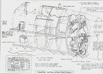
Here you go Geo, I found the works drawings for the Type 35 control fitting for FR Spits. Note that, as Darryl pointed out, the camera selector (low down, port side, beneath the longeron the 'door' is mounted to) would only be fitted if a multi-camera set up was present, and this drawing is a composite for various camera fits.
Note also the sighting marks on the canopy.
Hope this helps.
Note also the sighting marks on the canopy.
Hope this helps.
Attachments
Crimea_River
Marshal
Nice dig Terry.

meatloaf109
1st Lieutenant
Andy described it the way I would do it also.
T Bolt
Colonel
Nice drawing there Terry. I've already saved it for future reference
Airframes
Benevolens Magister
Thanks Glenn. That's just one of a number, showing the set up of everything from camera positions, to camera mounts, heaters and so on for various Marks of PR Spit, and there are more for fighter Spits, covering everything from wing construction, armament set up, control and fuel line runs etc.
They're mainly from the works drawings reproduced in the Shacklady Spitfire 'bible', and a few other references I have, so if there's anything else you think might be useful let me know and, if I have it, I'll send it via e-mail.
They're mainly from the works drawings reproduced in the Shacklady Spitfire 'bible', and a few other references I have, so if there's anything else you think might be useful let me know and, if I have it, I'll send it via e-mail.
Users who are viewing this thread
Total: 1 (members: 0, guests: 1)