Fw-190: the roots of the great roll rate?

Ad: This forum contains affiliate links to products on Amazon and eBay. More information in Terms and rules

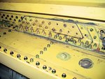
Photo 1: rear spar (among other items), slightly damaged bent.
Drawing (Seafire): the spars are within the red ellipses, the item marked with arrow attaches to the main spar's lower beam
Photo 2: attachment point for the rear spar should be somewhere, there...?
Photo 3: attachment point/area for the front spar - looks like it means business.

So maybe it is not a 99:1 between the load ratios of the front and rear spar; 90:10?

spars2.JPG
 
As I have understood it, at least in late 30s and early 40s single spar design meant a wing which main torsional box was formed by a heavy main/front spar and the skin between it and the leading edge and in a two spar wing the main torsional box was formed by a front and a rear spars and the skins between them. Look Morgan's and Shacklady's or Price's Spitfire books, IIRC in those they say that Spitfire had a single spar wing, and at least here in Finland we say that 109 also had single spar wing even if both had a lighter rear spar.
And therein lies the problem, since (for whatever reason) experts call it a single-spar wing (and I've only ever seen that description in a 1940s "Flight" magazine,) others, less knowledgeable, read it, don't bother to do any research worthy of the name, and trumpet this "The Spitfire only had one spar" stuff, as an explanation for its alleged inferior performance, when we know that there were other factors involved, as well.
During tests, in 1940, RAF pilots found that, when flying the 109, they were capable of withstanding more G than in the Spitfire and Hurricane, and realised that it was due to the straight-out leg position of the 109 cockpit, which delayed the onset of blacking out, since the blood was slower to drain into the lower legs. (Very) late in 1940 this led to the two-bar rudder pedals, in both of our fighters, allowing the pilots to raise their feet for combat, and lower them for normal flight.
Pre-war, the Spitfire was built to withstand 10G, and, even before the war started, work was put in hand to increase it to 12G (the Hurricane was already at that stage, at least once it had all-metal wings,) mainly by increasing the strength of the main spar by use of better quality duralumin.
 
And therein lies the problem, since (for whatever reason) experts call it a single-spar wing (and I've only ever seen that description in a 1940s "Flight" magazine,) others, less knowledgeable, read it, don't bother to do any research worthy of the name, and trumpet this "The Spitfire only had one spar" stuff, as an explanation for its alleged inferior performance, when we know that there were other factors involved, as well.

BINGO!

I wonder if there are any stress analysis reports that show how much of the wing load the rear spar actually carries on the Spitfire.
 
Joe - I would have a hard time believing that a.) the entire wing from aft 'flap spar' to leading edge was Not considered in torque box analysis, and b.) that the first approach in the airframe structures analysis was Not to look at primary spar/cap construction as primary Bending (pure distributed load bending from cantilever support..

The second comment is that airframe structures guys usually take a conservative first pass at stress analysis -

The wild card for the Spit is that the wheelwell 'interrupts' the torque box integrity aft of the main spar.. From past experience I probably would take a look at the torque box resistance by considering only the 'box section' outboard of the wheel attach point and look hard at the torsion created by the aileron (and some % of lift distribution outboard of wheel well) to determine what the initial deflections could be. I would look at the load paths required to transfer the torque to the inner wing, and thence to the wing attach structure.

As to the flap spar. It has to have significant structural properties because a.) it must act as primary strength member to introduce flap loads to the wing, b.) it is a secondary but important contributor to the 'aft' torque box in which the wheel well is buried, and c.) it is primary bending structure to take out the vertical loads induced by the aileron.
 
Last edited:
Joe - I would have a hard time believing that a.) the entire wing from aft 'flap spar' to leading edge was Not considered in torque box analysis

Exactly Bill. Somewhere I would think someone considered this in the over-all analysis no matter how less "robust" (for a better description) the rear spar is when compared to the forward spar.

Another interesting angle to look at is within the maintenance manuals - I wonder if in a structural repair manual are there repair limits addressed with regards to the rear spar. If there are limitations on repairs, their size, ect, that would be the smoking gun to show that this component was considered in the torque box analysis. (I'm thinking like a mechanic now) :silly:
 
Mid-1940 two wings were tested to destruction, and found to resist a factor (G?) of 11-13 (when the design called for 8-10,) tested to an all-up weight of 6,200lbs; the test report is 17 pages, so there's no way that I can put it on here.
In February 1940, an instruction was issued, with regard to examination for skin wrinkling, after any "abnormal manouevres." Any wrinkling, at all, on the leading edge, forward of the mainspar, would lead to the wing being declared unserviceable, and due for replacement. Aft of the mainspar, between ribs 14-19, any wrinkle less than 1/10" (2.5mm) could be disregarded; any wrinkle deeper than that (or wrinkles of any depth in any other area of the wing) would necessitate examination of the wingroot bolts, and, if they were bent, wing and bolts were to be replaced.
There is a manual, on repairs, patching, etc., but it's umpteen pages long, and I've no idea if the rear spar is mentioned.
 
Last edited:
And therein lies the problem, since (for whatever reason) experts call it a single-spar wing (and I've only ever seen that description in a 1940s "Flight" magazine,) others, less knowledgeable, read it, don't bother to do any research worthy of the name, and trumpet this "The Spitfire only had one spar" stuff, as an explanation for its alleged inferior performance, when we know that there were other factors involved, as well...

I agree but that is a common problem with professional terms.

Juha
 
Mid-1940 two wings were tested to destruction, and found to resist a factor (G?) of 11-13 (when the design called for 8-10,) tested to an all-up weight of 6,200lbs; the test report is 17 pages, so there's no way that I can put it on here.

Edgar - a Destruct Test takes the airplane to Ultimate load to see a.) where the failure occurs, and b.) asks the question "Dit fail where I predicted it would fail". The Design Limit load for those conditions (Pre-yield or 'pre-wrinkling') and should be at 8-8.66 times the weight of the aircraft. Standard airframe structures philosopy was 8G Limit/12 G Ultimate. Plastic conditions exceeding Yield results in permanent deformation - usually resulting in writing off a makor componenet or the entire airframe

In February 1940, an instruction was issued, with regard to examination for skin wrinkling, after any "abnormal manouevres." Any wrinkling, at all, on the leading edge, forward of the mainspar, would lead to the wing being declared unserviceable, and due for replacement. Aft of the mainspar, between ribs 14-19, any wrinkle less than 1/10" (2.5mm) could be disregarded; any wrinkle deeper than that (or wrinkles of any depth in any other area of the wing) would necessitate examination of the wingroot bolts, and, if they were bent, wing and bolts were to be replaced.
There is a manual, on repairs, patching, etc., but it's umpteen pages long, and I've no idea if the rear spar is mentioned.

Note: Destruct tests were performed with lead/sand bag weights distributed to approximate static loads and could not model asymmetric aero loads or any complex condition..
 
Back to the Fw190 rollrate. Could it be that the general structure construction was responsible for the excellent performance. At all planes I know both wing halves were attached to the side of fuselage. At the Fw190 the wing is one part with one main spar running through the whole wing assembly and was bolted to the fuselage from below. One pic is from FlugWerk and the other a scan from the Wolfgang Wagner's book " KURT TANK KONSTRUKTEUR UND TESTPILOT BEI FOCKE WULF .
cimmex
IMG_0001.jpg
g-fw190-structure1.jpg
 
I cannot say, but 190 wasn't the only plane with one piece wing, for ex Brewster Buffalo had one and that structure had also its drawbacks, at least that was the opinion of S/L Churchill in his assestment on Brewster Buffalo as a combat plane. He was the leader of the Eagle sqn (RAF 71 Squadron) consisting American volunteer pilots. They were given three Brewsters, which must also have been 339Bs. He filed this report in October 1940.

"It is strongly recommended that this type should on no account be considered as a fighter without considerable modification.

The wings are not bolted to a centre section but appear to have a common main rear spar located through the fuselage. Changing wings in the event of accidents will therefore be uneconomical and slow.

The elevator is actuated by a push-pull tube. While this is a positive method of operation it is feared than an explosive shell or even a bullet . . . may shatter or collapse it. Experience has proved how much punishment the twin cable can stand without breaking down..."

So even the push-pull tube had its downside.

And as has wrote earlier 190 lost its lead in high speed, P-51B rolled better at 360+mph IAS and Tempest V at 365+mph IAS at 10000ft.

Juha
 
Last edited:
I'd like to know how much of the load on the Spitfire's rear,auxiliary or secondary (depending what you are reading) spar is transfered to the main wing spar.
Steve
 
The Fw190 elevator control. From the stick to the bellcrank at bulkhead 8 was by rod. From there back to the elevator differential unit it was cables. It then switch back to rod. For the rudder it was rods to the rudder differential unit and then cables to the elevator. Only the ailerons were completely rod.
 
I

And as has wrote earlier 190 lost its lead in high speed, P-51B rolled better at 360+mph IAS and Tempest V at 365+mph IAS at 10000ft.

Juha

360 IAS are around 432 TAS at 10k so very uncommon speed
 
360 IAS are around 432 TAS at 10k so very uncommon speed

I knew it was a high speed, even if I thought that 360mph IAS at 10 000 ft means 419mph TAS. I used it only to indicate that the wing of 190 wasn't exeptional stiff, but it had a good solid wing and IMHO one important factor to its high roll rate, besides it wing platform and profile, was the use of Frise ailerons, which had the downside of being difficult to rig optimaly, one of complains Quill had with Spitfire's ailerons (also Frise -type) so they slow down acceptance tests.

Juha
 
I'd like to know how much of the load on the Spitfire's rear,auxiliary or secondary (depending what you are reading) spar is transfered to the main wing spar.
Steve

Not possible without access to the airframe design/structures analysis - unless you want to start from scratch using the detail design and BOM, the Aero loads as calculated and presented to the structures group.
 
Back to the Fw190 rollrate. Could it be that the general structure construction was responsible for the excellent performance. At all planes I know both wing halves were attached to the side of fuselage. At the Fw190 the wing is one part with one main spar running through the whole wing assembly and was bolted to the fuselage from below. One pic is from FlugWerk and the other a scan from the Wolfgang Wagner's book " KURT TANK KONSTRUKTEUR UND TESTPILOT BEI FOCKE WULF .
cimmexView attachment 215551View attachment 215552

The Mustang had complete continuity with spar structure (all) via wing (left and right) attaching to each other at the Centerline.
 
V- you need to be careful about the "rule of thumb" calculations offered to convert from IAS to TAS. The range of those methods will give TAS of 432(high) to 402 (low and very close to my charts) when compared to STP altitude charts. From extrapolation from my handy Vest Pocket Aero Handbook I pick off ~ 403mph TAS.

The closest "rule of thumb" method of dividing altitude by 1000, multiplying by 3, adding 7kts to the IAS yields:
360 x .869 =312.84kts + 10,000/1000 (=30) + 7 = 349.84kts/.869 = 402.57mph at 10,000 feet
 

Users who are viewing this thread

Back