Messerschmitt Me 323 Gigant

Ad: This forum contains affiliate links to products on Amazon and eBay. More information in Terms and rules

A4K

Colonel
14,998
2,827
Dec 17, 2007
The back of beyond
G'day !

I've already asked this question on another of these forums, but I ask it again here in the hope that someone can help.

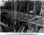
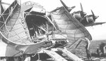
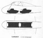
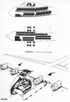
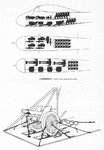
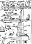
Does anyone have any information and /or photos regarding the internal wing structure of the Me 321/ 323 as visible within the fueslage- specifically, was the wing structure 'open' and visible within the fueslage, or covered, ie. built as a one piece wing and then attached to the fueslage ?

I'm building the Italeri 1:72 Me 323D-1 kit at the moment, and they have moulded it as a solid wing, yet if soldiers could be carried seated in a two-tier arrangement, then this area must have either been open, or had removable panels (or maybe they just stripped the canvas ?)
The internet seems sadly lacking in structural info on many of the german types.

Any info on the cockpit would be appreciated also, as the only pictures I have of this area are from a computer-game site I found (although it seems to be fairly comprehensive - I can only presume they had access to some good reference photos)

Cheers!
 
Danke Adler and Thorlifter !

I'd seen these pics before on the forum and elsewhere on the net, but the only one in which you can 'sort of' see into the wing area is the picture of them loading the DB 601(?) engine.

It does show atleast that the rear section atleast was open - you can clearly see the gunners glazing on both sides where the wing trailing edges meet the fueslage. Just still not sure if the whole area was open or not. (As E-versions of the Me 323 had turrets in the wings, there must have been gunner's access into this area atleast)

A drawing of the fueslage structure found elsewhere shows that the fueslage was formed to fit the wing, suggesting the wing was fitted as a one piece structure.

Any clues?
 
Pictue of a wing being assembled from the book Messerschmitt Me 321/323 by H.P. Dabrowski
 

Attachments

  • 323.JPG
    323.JPG
    114.6 KB · Views: 827
Great picture Midrow, thanks!

Will be a BIG help If I have to detail this area ! (It does seem to point to the fact that it probably was just an open structure, don't you think ?)
 
Great picture Midrow, thanks!

Will be a BIG help If I have to detail this area ! (It does seem to point to the fact that it probably was just an open structure, don't you think ?)

I dont know a whole lot about this aircraft. I would have to dig deeper on the subject. The area would not be completely empty though. You would have cross beams used to hold together the wing spars. From the little research I did the fuel tanks where mounted in the wings but not for sure where. I would have to dig deeper on that subject.

On the six engined version a flight engineer sat inside both wing's between the two innermost engines and was responsible for monitoring the engines on each side.

Another note of interest is the engines. The leading edge of the wing had to covered in sheet metal. Reason was because the engine's often caught fire if left idling for a long period of time.

Hope this help's as Im off to work.
 
Thanks again MiCdrow (sorry about the typo..!)

It's really starting to sound as if this area would have been fairly open, that is, with little or no covering at all... would still appreciate anything anyone can come up with though to maybe help clarify it a bit better.

Thanks again, and a Happy Christmas and all the best for the new year to all of ya's - I'm off work for a week or so, so won't be online again till 03 Jan.

Till then, have a good one!


No problem, Im curious on the exact location of the fuel tanks now so will see if I can dig up anything more on the fuselage frame and mountings
 
Thanks again Micdrow!

The top picture was the best reference I'd found before you'd sent that photo of them constructing the wing (what a job!), and was what I was referring to when I made the comment about the structure being formed to fit the wing.

It still leaves a lot to speculation as to how much of the main wing structure was visible though. I'll probably end up detailing the whole lot as exposed framework unless I find any info to the contrary.

Thanks for your comment on the engineer positions too- I feel sorry for them being stuck in the wings during the flight! I once read about an engineer who was shut up by accident in the wing of a Sunderland - the draught was so strong and cold in the plane that the radio op shut the access door while he was in there and they only realized something was up when they heard alot of swearing and banging coming from the wing!

Makes you wonder how it must have been for two engineers to be purposely stationed there in a six motored giant...
 
Makes you wonder how it must have been for two engineers to be purposely stationed there in a six motored giant...

Its diffently a postion I would not want to be in during combat thats for sure.
 
Hi Evan, Its a Opel Blitz halftrack Maultier (Mule). this was developed from . a Blitz 3-ton-s truck. Proberably the most reliable and servicable truck the germans used during ww2. Based on a pre-war commercial design, with a 3.6litre Buick engine. Incidently,the track running gear was a copy of the British Carden-LLoyd running gear. Even though they had developed a improved version themself,s it never went into production. Although Merecedes Benz were involved in the manufacturer of Opel Blitz trucks, and engines, etc. it was the Opel (a subsidery of GM) design that proved to be the most successful, compared to many military specific design,s.
Hope this is not too much of a digression, in reply to simple qery. all the best Leonard.
 
Here some are Diagrams.........:D
 

Attachments

  • me32301ud0.jpg
    me32301ud0.jpg
    33.7 KB · Views: 579
  • me32302pf6.jpg
    me32302pf6.jpg
    98.2 KB · Views: 722
  • 00000000000000000000.jpg
    00000000000000000000.jpg
    9.1 KB · Views: 459
  • Me323_10.jpg
    Me323_10.jpg
    18.7 KB · Views: 391
  • 00000.jpg
    00000.jpg
    33.4 KB · Views: 425
  • me32302pf7.jpg
    me32302pf7.jpg
    98.2 KB · Views: 476
  • me32303fs6.jpg
    me32303fs6.jpg
    92.6 KB · Views: 507
  • He111_Me321.jpg
    He111_Me321.jpg
    5.4 KB · Views: 443
Very interesting. These photos and diagrams shed a lot of light on the first heavy transport plane. By the way B-17 Engineer those are words from the song "Lenningrad" by Billy Joel in your signature.
 
Hallo A4K,

I'm not sure if you are still interested in, but these can come in handy.I know these are not of a good quality but I've found drawings a bit small and had to make them enlarged.

Source unknown.
 

Attachments

  • Me323_1.jpg
    Me323_1.jpg
    305.5 KB · Views: 1,602
  • Me323_2.jpg
    Me323_2.jpg
    310.5 KB · Views: 1,122

Users who are viewing this thread

Back