Nice work so far!
Navigation
Install the app
How to install the app on iOS
Follow along with the video below to see how to install our site as a web app on your home screen.
Note: This feature may not be available in some browsers.
More options
You are using an out of date browser. It may not display this or other websites correctly.
You should upgrade or use an alternative browser.
You should upgrade or use an alternative browser.
Stripped down Mosquito MK IV 1/32
- Thread starter BertUS
- Start date
Ad: This forum contains affiliate links to products on Amazon and eBay. More information in Terms and rules
More options
Who Replied?- Thread starter
- #302
BertUS
Senior Airman
It's time for some free work again, so I've started on the airlerons, before I start adding all kinds of details in the wing and I can't reach anything anymore
So I work a little bit off the wing of the Revell model, because although I have a number of drawings, they still differ from each other, especially in terms of dimensions. So you have to assume something and that's why I chose the Revell model (the HK model is nicer, but to buy a reference thing for 160 euros now, mwah, the Harley just got through it here in the house") )
)
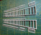
Anyway, the first step is often the drawing work

Then cut a batch

and paste

What's the difference with making tracks for a tank?
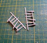
Tightening and holding on fragile things when I do this I use a very specialist clamp that I can adjust to press force, I work with purely simple tools but this was well worth the investment

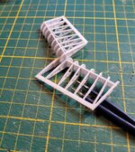
Well, then you have a staircase that still needs to be sanded into shape, and that has to be done with care, because before you know it the ribs will shoot in every direction again

But perseverance wins and you still get something of this, still had to cut some loose and realign, but okay, for the time being these can harden for a while, then put the crossheads on and think about how they can be attached to the wing, movable of course

Well, I'll continue with the flaps, that's easy to write over, just CTRL C and CTRL V of the text, just different places
So I work a little bit off the wing of the Revell model, because although I have a number of drawings, they still differ from each other, especially in terms of dimensions. So you have to assume something and that's why I chose the Revell model (the HK model is nicer, but to buy a reference thing for 160 euros now, mwah, the Harley just got through it here in the house
)Anyway, the first step is often the drawing work
Then cut a batch
and paste
What's the difference with making tracks for a tank?
Tightening and holding on fragile things when I do this I use a very specialist clamp that I can adjust to press force, I work with purely simple tools but this was well worth the investment
Well, then you have a staircase that still needs to be sanded into shape, and that has to be done with care, because before you know it the ribs will shoot in every direction again
But perseverance wins and you still get something of this, still had to cut some loose and realign, but okay, for the time being these can harden for a while, then put the crossheads on and think about how they can be attached to the wing, movable of course
Well, I'll continue with the flaps, that's easy to write over, just CTRL C and CTRL V of the text, just different places
Vic Balshaw
Major General
Beautiful bit of workmanship.
- Thread starter
- #304
BertUS
Senior Airman
Thanks
Crimea_River
Marshal
Nice! And I like your clamp!.
- Thread starter
- #307
BertUS
Senior Airman
Thanks guys
Andy, I can sell your some, just 50 US dollar
Andy, I can sell your some, just 50 US dollar
Crimea_River
Marshal
No thanks! I have two but I don't use them as clamps!
Vic Balshaw
Major General
Same here, bit its an idea.
Good work so far!
- Thread starter
- #311
BertUS
Senior Airman
The flaps, I wrote that a simple CTRL C, CTRL V were sufficient, but in practice that turned out to be a lot more work. Now have a few days off so could continue, next to the animals, household, the motorcycle and so on.
Anyway, the flaps, I started with the inner ones first
There are a few openwork ribs, so with a house drawing and much more carving,

So I finally got this

And you have to put that together, nice and fragile work that you have to take the time for

After letting the glue harden a little longer, the rest was glued on and the shape sanded in

well and then the second
Well CTRL C, CTRL V so
https://modelbrouwers.nl/media/cache/83/58/83589108bc5c6b7801876e96ed78a51d.jpg[img]
Kind of the same story as above, how boring, but in the end, you have 2
[ATTACH=full]699732[/ATTACH]
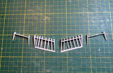
Then the outer one, the first Mossies had 1 flap, but after extending the engine nacelle, these were divided (although I have to look for how to make that engine nacelle at the rear, there is not much to be found about it and what is there speaks sometimes against each other
Here's the inner one and the outer one in the basic shape
[ATTACH=full]699733[/ATTACH]
And with some fiddling you get these things, although they still have to be sanded neatly
[ATTACH=full]699734[/ATTACH]
And while I was looking at the drawing, I suddenly noticed that I had the ribs at the wrong angle on the inner flaps
so first like this
[img]https://modelbrouwers.nl/media/cache/2b/c8/2bc86286d79adb4213dbbe7f3b18ef76.jpg[img]
The ribs, run parallel to the two solid inner ones. But the drawing showed something different
[ATTACH=full]699735[/ATTACH]
Yep, they have to be loosened, converted and glued again
Well, it worked
And then also a photo with the parts already present to make the wings
[ATTACH=full]699736[/ATTACH]
So still h
Anyway, the flaps, I started with the inner ones first
There are a few openwork ribs, so with a house drawing and much more carving,
So I finally got this
And you have to put that together, nice and fragile work that you have to take the time for
After letting the glue harden a little longer, the rest was glued on and the shape sanded in
well and then the second
Well CTRL C, CTRL V so
https://modelbrouwers.nl/media/cache/83/58/83589108bc5c6b7801876e96ed78a51d.jpg[img]
Kind of the same story as above, how boring, but in the end, you have 2
[ATTACH=full]699732[/ATTACH]
Then the outer one, the first Mossies had 1 flap, but after extending the engine nacelle, these were divided (although I have to look for how to make that engine nacelle at the rear, there is not much to be found about it and what is there speaks sometimes against each other
Here's the inner one and the outer one in the basic shape
[ATTACH=full]699733[/ATTACH]
And with some fiddling you get these things, although they still have to be sanded neatly
[ATTACH=full]699734[/ATTACH]
And while I was looking at the drawing, I suddenly noticed that I had the ribs at the wrong angle on the inner flaps
so first like this
[img]https://modelbrouwers.nl/media/cache/2b/c8/2bc86286d79adb4213dbbe7f3b18ef76.jpg[img]
The ribs, run parallel to the two solid inner ones. But the drawing showed something different
[ATTACH=full]699735[/ATTACH]
Yep, they have to be loosened, converted and glued again
Well, it worked
And then also a photo with the parts already present to make the wings
[ATTACH=full]699736[/ATTACH]
So still h
Attachments
Last edited:
Vic Balshaw
Major General
From what has come through looks painstakingly good but the last 5 pics are not showing at my end. 
- Thread starter
- #313
BertUS
Senior Airman
Vic, just like the whole project, I've to do things twice
EDIT
Huh, why they are now as attachtments, I overwrite the ATTATC line
EDIT
Huh, why they are now as attachtments, I overwrite the ATTATC line
Crimea_River
Marshal
Fiddly stuff but looks good.
Nicely done so far!
- Thread starter
- #317
BertUS
Senior Airman
So, best wishes for 2023, it's still allowed right?
I skipped a week because I played with Lego technic, which is quite addictive, but it is also an expensive side hobby, even if you get the sets from Marktplaats. Anyway, between visits to the ophthalmologist and such (so tomorrow I can go under the knife and hopefully I will see something normal again) I have done something, although I am not satisfied with everything and I am looking at how I can do that need to improve (it won't be me doing things over again)
So I continued with the wings and made the plates for the flaps, so the flaps turn along here, all photos are mss clearer than the previous sentence.
First the ribs

Then we stick a thin sheet of styrene against it with some overhang, where I already cut the holes

We repeat the same for the second

Now those pictures are there, but not really neat, so we will demolish and replace them as soon as I have prepared the installation of the flap control.
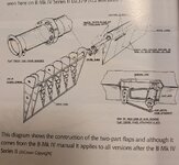
The flap control is hidden in the protruding point at the rear of the engine nacelle, the flaps are set in the chosen position by means of a hydraulic cylinder, so the controls are located on the right side of the main dashboard in front of the pilot and are operated with levers that are set in certain positions. set, so 15, 30 and 60 degrees down, if I'm right, I'm not a pilot.
Now it is a "easy" for the standard aircraft builders saw or cut the flaps loose from the wing and glue them in the desired angle, well, of course I have to make it much more difficult for myself
Judging from the sketch I understood the principle, but you also have to make it AND it has to be movable, so a lot of thinking about materials (printing would be the easiest, but that is very fragile with the resin I have now)
So first I made a sketch in SolidWorks to understand the principle.
[video=youtube]
View: http://youtube.com/watch?v=-FuMoKpQOEI%5B/video%5D
Ah, that makes it a bit clearer. Well first make those U-shaped pivots. I don't have any tube material, so first make rings yourself

So paste the pictures in a rough shape, so first square, then 8 angular, then 16 angular and then sand it smooth

And you get something like that with just a bit of pasting


Just loosen it up and you've got it

In the same way we also make the basic shape for the cylinder and we make a fixed pivot point for the torque, on the video that is the triangle
Lay down for a while

And we crochet everything together with pain and effort

Well, now I have to maken it nice and clear, add details en hopefully I can see better after the surgery
I skipped a week because I played with Lego technic, which is quite addictive, but it is also an expensive side hobby, even if you get the sets from Marktplaats. Anyway, between visits to the ophthalmologist and such (so tomorrow I can go under the knife and hopefully I will see something normal again) I have done something, although I am not satisfied with everything and I am looking at how I can do that need to improve (it won't be me doing things over again)
So I continued with the wings and made the plates for the flaps, so the flaps turn along here, all photos are mss clearer than the previous sentence.
First the ribs
Then we stick a thin sheet of styrene against it with some overhang, where I already cut the holes
We repeat the same for the second
Now those pictures are there, but not really neat, so we will demolish and replace them as soon as I have prepared the installation of the flap control.
The flap control is hidden in the protruding point at the rear of the engine nacelle, the flaps are set in the chosen position by means of a hydraulic cylinder, so the controls are located on the right side of the main dashboard in front of the pilot and are operated with levers that are set in certain positions. set, so 15, 30 and 60 degrees down, if I'm right, I'm not a pilot.
Now it is a "easy" for the standard aircraft builders saw or cut the flaps loose from the wing and glue them in the desired angle, well, of course I have to make it much more difficult for myself
Judging from the sketch I understood the principle, but you also have to make it AND it has to be movable, so a lot of thinking about materials (printing would be the easiest, but that is very fragile with the resin I have now)
So first I made a sketch in SolidWorks to understand the principle.
[video=youtube]
View: http://youtube.com/watch?v=-FuMoKpQOEI%5B/video%5D
Ah, that makes it a bit clearer. Well first make those U-shaped pivots. I don't have any tube material, so first make rings yourself
So paste the pictures in a rough shape, so first square, then 8 angular, then 16 angular and then sand it smooth
And you get something like that with just a bit of pasting
Just loosen it up and you've got it
In the same way we also make the basic shape for the cylinder and we make a fixed pivot point for the torque, on the video that is the triangle
Lay down for a while
And we crochet everything together with pain and effort
Well, now I have to maken it nice and clear, add details en hopefully I can see better after the surgery
Airframes
Benevolens Magister
Excellent !
You're really doing some fantastic work here.
You're really doing some fantastic work here.
- Thread starter
- #319
BertUS
Senior Airman
Thank you so much
Vic Balshaw
Major General
You lost me after the first pic, but then it twigged and I caught up. What amazing stuff your doing. Hope all goes well for tomorrow.
Users who are viewing this thread
Total: 1 (members: 0, guests: 1)