Nice work so far!
Navigation
Install the app
How to install the app on iOS
Follow along with the video below to see how to install our site as a web app on your home screen.
Note: This feature may not be available in some browsers.
More options
You are using an out of date browser. It may not display this or other websites correctly.
You should upgrade or use an alternative browser.
You should upgrade or use an alternative browser.
Stripped down Mosquito MK IV 1/32
- Thread starter BertUS
- Start date
Ad: This forum contains affiliate links to products on Amazon and eBay. More information in Terms and rules
More options
Who Replied?N4521U
Plastic Pirate
Oh boy I do love the look of 3D mechanical drawings.
Even when I was doing 2D with a pencil.
But to have the tools to print them, I drool.
Very nice work.
Even when I was doing 2D with a pencil.
But to have the tools to print them, I drool.
Very nice work.
- Thread starter
- #443
BertUS
Senior Airman
Well and on......................
I have not been idle in terms of construction, although it is not fast if you do this in wasted hours
I haven't done much more work on the landing gear yet, but I have done some more work on the enlarged version of the tail construction and now I just have to finish it a bit neater. A comment for the rest of this report, I only use many of the printed parts as examples to recreate them myself, for various reasons and certainly a reason to start printing with the standard resin, in the hope that the results are better than now. On the other hand, the scratched parts are just not tight, precise and neat enough, so I am constantly making trade-offs.......... pfffff, I hadn't written this before: )
Anyway, here are the places of the tail where I tried to make the construction sort of work so that it is visible how the Mossie was put together. You really get full respect for the illustrators of that time, because I cannot get the correct rudder reading with my digital drawing and 3D images

 [/URL]


For the rest I started with the cockpit and wing section that is in the fuselage
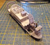
The first photos show the fuel tanks that are located in the wing, at the front and rear you can see the supports for the bomb load and in the middle there is a kind of passage for the cable work with which the bomb rack was hoisted up. The hand winch was located in the rear of the hull
In the photo of the top you can see the radio and the HT/LT units that are actually mounted on the wing top. I can already see that I'm going to have quite a bit of trouble with the finishing touches.


A few days later I had finished the top a little further, including the beginning of the cabling. In the photo of the part on the wooden surface you can see a piece of the outer wall where I left a bite out of it so that you can see the bomb bay from the side, the bomb hatches will then be hung at the bottom


I have not been idle in terms of construction, although it is not fast if you do this in wasted hours
I haven't done much more work on the landing gear yet, but I have done some more work on the enlarged version of the tail construction and now I just have to finish it a bit neater. A comment for the rest of this report, I only use many of the printed parts as examples to recreate them myself, for various reasons and certainly a reason to start printing with the standard resin, in the hope that the results are better than now. On the other hand, the scratched parts are just not tight, precise and neat enough, so I am constantly making trade-offs.......... pfffff, I hadn't written this before: )
Anyway, here are the places of the tail where I tried to make the construction sort of work so that it is visible how the Mossie was put together. You really get full respect for the illustrators of that time, because I cannot get the correct rudder reading with my digital drawing and 3D images
For the rest I started with the cockpit and wing section that is in the fuselage
The first photos show the fuel tanks that are located in the wing, at the front and rear you can see the supports for the bomb load and in the middle there is a kind of passage for the cable work with which the bomb rack was hoisted up. The hand winch was located in the rear of the hull
In the photo of the top you can see the radio and the HT/LT units that are actually mounted on the wing top. I can already see that I'm going to have quite a bit of trouble with the finishing touches.
A few days later I had finished the top a little further, including the beginning of the cabling. In the photo of the part on the wooden surface you can see a piece of the outer wall where I left a bite out of it so that you can see the bomb bay from the side, the bomb hatches will then be hung at the bottom
Vic Balshaw
Major General
Incredibly detailed work, you have my admiration. 

- Thread starter
- #445
BertUS
Senior Airman
Thanks Vic
Crimea_River
Marshal
With Vic. Amazing stuff.
Looks good so far!
- Thread starter
- #449
BertUS
Senior Airman
I did some more work on the hobby this weekend, so I read through my pattern drawing course again and started with the nose
This must be present, but at the same time the interior must remain visible
So I started sticking


As can be seen in the last photo, no success, so we started attempt 2

To make a very long story very short
"worthless"
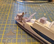
so we started something different. The photos of the bomb bay show some kind of power divider, at least I think it is something like that, but hey, that had to be recreated too
So we take 2 pieces of 1 mm strip and then stick them together into a block of 2 thick and 5 long. Then wait until the glue has hardened and then file a few slots with a triangular file and treat them with sandpaper until it looks like 3 pipes.
With a few small pieces of strip on the back it looks like a bit more and I can clamp it in my vice clamp thing (there is a real one on the way, they say, but I don't believe DPD so much) and then use my newly purchased P&D set to create a few rounds made of 1.5 mm.

Oh well, pasting is simpler

Then a quick strip and a few more rounds
And presto, done

Now just stick it in the bombbay

Also installed some pipes in the bombbay
It is not entirely in accordance with the photo reference, but I thought this was too much fiddling (I'm afraid I'll have a lot more to deal with)

And the cockpit has already been filled a bit with some parts from the previous versions


This must be present, but at the same time the interior must remain visible
So I started sticking
As can be seen in the last photo, no success, so we started attempt 2
To make a very long story very short
"worthless"
so we started something different. The photos of the bomb bay show some kind of power divider, at least I think it is something like that, but hey, that had to be recreated too
So we take 2 pieces of 1 mm strip and then stick them together into a block of 2 thick and 5 long. Then wait until the glue has hardened and then file a few slots with a triangular file and treat them with sandpaper until it looks like 3 pipes.
With a few small pieces of strip on the back it looks like a bit more and I can clamp it in my vice clamp thing (there is a real one on the way, they say, but I don't believe DPD so much) and then use my newly purchased P&D set to create a few rounds made of 1.5 mm.
Oh well, pasting is simpler
Then a quick strip and a few more rounds
And presto, done
Now just stick it in the bombbay
Also installed some pipes in the bombbay
It is not entirely in accordance with the photo reference, but I thought this was too much fiddling (I'm afraid I'll have a lot more to deal with)
And the cockpit has already been filled a bit with some parts from the previous versions
Attachments
Crimea_River
Marshal
Great stuff Bert. That item you built is called the "Fuel Gallery" and it's basically the main collection point for all the fuel lines from the tanks to the engines.


- Thread starter
- #451
BertUS
Senior Airman
Aha, great point, something learned,but ....now I have to make some running lines
Crimea_River
Marshal
I can post more to help with that if you need routings.
- Thread starter
- #453
BertUS
Senior Airman
Yes please
I needed the routing to the engines,and the part after bulkhead 4,the cables for the steering part ,I know,but the electric part in section between bh. 3 and 4 ander aft till bh 7.I didn't make it 100o/o accuraat but will try to reach the 60
I needed the routing to the engines,and the part after bulkhead 4,the cables for the steering part ,I know,but the electric part in section between bh. 3 and 4 ander aft till bh 7.I didn't make it 100o/o accuraat but will try to reach the 60
Crimea_River
Marshal
Will try to get you some of that before the weekend.
- Thread starter
- #455
BertUS
Senior Airman
Thanks,Andy
Crimea_River
Marshal
Fuel routings for the B.35. I don't have the same for the B.IV.


Center tanks in bomb bay looking forward with fuel gallery at right: (pic by Mel Johnstone). The pic is of B.35 RS712 in Weeks' collection. The curved frame is for the long range tank and the angle frames are for a postwar storage box so would not be on your plane.

Center tanks in bomb bay looking forward with fuel gallery at right: (pic by Mel Johnstone). The pic is of B.35 RS712 in Weeks' collection. The curved frame is for the long range tank and the angle frames are for a postwar storage box so would not be on your plane.
- Thread starter
- #457
BertUS
Senior Airman
Ah, really great,it will be little details, but will give my model more dimension
Crimea_River
Marshal
Good work so far!
- Thread starter
- #460
BertUS
Senior Airman
I think this is a later one, but the details are usefulBertUS regarding "......but the electric part in section between bh. 3 and 4 ander aft till bh 7.I didn't make it 100o/o accuraat but will try to reach the 60" can you please clarify what you are after? I don't have anything on the B.IV electrics and the B35 stuff between BH3 and 4 will be very different - I assume you mean the area above the bomb bay or are you looking for in the bomb bay? I have the below pic of unknown source and I don't know what Mosquito this is.
View attachment 750963
I am looking for some details of the airtanks, routing of the electric cables on starboardsite from bh 3 till 5. Foto the parts after 5 i have refrencepics. After all the model will be in the basic a mk IV,but with some little details from later versions.
I also can't find really nice pics of the wingspar,with parts and cables mounted on it have to find out how the junctions are of the spars in the middle of the wings,so,not the part in side the fuselage but in the wings
Users who are viewing this thread
Total: 1 (members: 0, guests: 1)