Super detailing Guillow's P-51D Mustang

Ad: This forum contains affiliate links to products on Amazon and eBay. More information in Terms and rules

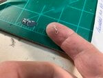
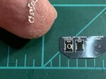
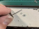
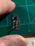
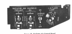
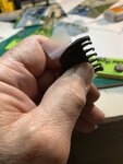
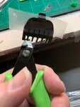
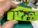
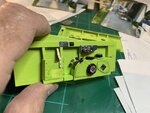
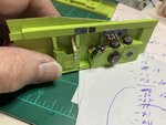
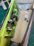
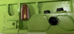
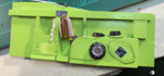
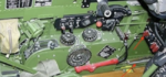
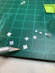
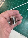
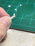
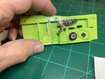
Having (now) established my credentials of lacking common sense, it should therefore come as no surprise that I have decided such mundane items as bolts simply will not do and have decided the great task of fabricating my own switches that I felt would better reflect the real thing.

After all, I have to justify all those days shopping at the local arts and craft stores. What better way to justify needless expense of money on such insignificant items that lack any value whatsoever and spend an extraordinarily (additional) amount of time?
 

Attachments

  • P-51 stencils & assy # 20.jpeg
    P-51 stencils & assy # 20.jpeg
    46.4 KB · Views: 48
  • P-51 stencils & assy # 22.jpeg
    P-51 stencils & assy # 22.jpeg
    47 KB · Views: 48
  • P-51 stencls & assy # 21.jpeg
    P-51 stencls & assy # 21.jpeg
    39.6 KB · Views: 45
The next step involved shaping the shanks from pins into slight bulges that is indicative of the switches. Several passers through white glue were necessary to achieve the desired thickness as well as compensating for the inevitable shrinkage when dried.

I then used a MicroMark small punch-&-die set to punch out a small circle to fabricate a variable switch at the right side of the control panel. There were several attempts to get the small vane portion to shape. I have ordered small switch accessories from GasPatch, knowingly well ahead of time that their switches at 1/32nd scale will be too small for my needs at 1/15th scale. Still, more shopping, eh?
 

Attachments

  • P-51 stencil & assy # 24.jpeg
    P-51 stencil & assy # 24.jpeg
    69.3 KB · Views: 39
  • P-51 stencils & assy # 25.jpeg
    P-51 stencils & assy # 25.jpeg
    36.3 KB · Views: 40
As can be seen from this zoomed photo, the small links that were cut away from the necklace chain are very distinctive and much more true to representing the rings round a switch than a simple bolt turned upside down. Still a bit more detailing is in the works.
 

Attachments

  • P-51 stencils & assy # 11.jpeg
    P-51 stencils & assy # 11.jpeg
    40.5 KB · Views: 45
Some additional research (actually, staring at this image for several hours until going cross-eyed) revealed that the switches were also safetied. 'At least this is my interpretation. Also the image suggested that the switch controls are vertically activated when in fact they are moved laterally. My initial gluing of the switches were also in the vertical position until other photos & documentation helped me to determine that this was not the case. So I was fortunate that the glue had not completely dried and was able to reposition the switches to reflect their true movement.
 

Attachments

  • P-51 Stencils & assy # 30.png
    P-51 Stencils & assy # 30.png
    45.2 KB · Views: 49
I was at loss as to how to fabricate the safety covers. Other pictures also show them painted red.

I was practicing personal hygiene in case I needed to "come up clean" for the misses, when I realized I had the safety covers right in front of me. Fortunately, the guard rails to the shaver were suddenly determined not to be my size and therefore were readily made "available."

After making do with the snips, they were duly painted red.
 

Attachments

  • P-51 stencils & assy # 18.jpeg
    P-51 stencils & assy # 18.jpeg
    47.8 KB · Views: 39
  • P-51 stencils & assy # 10.jpeg
    P-51 stencils & assy # 10.jpeg
    43.2 KB · Views: 46
  • P-51 stencil & assy # 8.jpeg
    P-51 stencil & assy # 8.jpeg
    77.3 KB · Views: 47
I have no idea as to whether or not the safety guards were necessary or whether I fabricated them correctly as the best images I could come up with as of this writing were what I had to use. Perhaps someone could lend a new perspective?

As can also be seen from this image, no safety guards were there. So there is a contradiction here. Or at least some inconsistency.
 

Attachments

  • Stenciles & assy # 31.png
    Stenciles & assy # 31.png
    47.8 KB · Views: 43
Last edited:
The completed control panel was then glued to the left side. I had to "fudge" a bit and the panel was affixed a bit higher and a bit rearwards nearest the vertical support column for better surface adhesion.

I hope you have enjoyed my presentation and the build of the left side continues. Thank you all for looking in.

Gary
 

Attachments

  • P-51 stencils & assy # 26.jpeg
    P-51 stencils & assy # 26.jpeg
    53.7 KB · Views: 59
  • P-51 stencils & assy # 27.jpeg
    P-51 stencils & assy # 27.jpeg
    52.2 KB · Views: 57
  • P-51 stencils & assy # 28.jpeg
    P-51 stencils & assy # 28.jpeg
    51.1 KB · Views: 58
Wurger & Airframes,
Thank you sirs, Airframes, I'm sure you must be aware of the superb quality of Peter's work in Britmodeller of Lope's Hope as well as knowledge of warbirds one general. So your compliments were greatly appreciated.
 
Good evening to everyone. I thought I would post a comparison shot of "before" and (almost) "after" pictures of the cockpit left side panel. I still have a few more details such as the throttle quadrant and landing gear lever but I just couldn't resist a morale boosting photo-shoot. Every once in awhile, all of us modelers could use a little bit of our own encouragement now and then, to help us know we're actually making progress.

I realize that the small (tiny) switches to the radiator controls located by the pilot's left shoulder, are a bit oversized, but I really didn't pay attention until it was almost too late. By then, I figured it doesn't look too bad and next time, I'll do better.
 

Attachments

  • P-51 cockpit model -# 1.jpeg
    P-51 cockpit model -# 1.jpeg
    46.4 KB · Views: 39
  • P-51 cockpit model -# 2.jpeg
    P-51 cockpit model -# 2.jpeg
    57.5 KB · Views: 41
As with many things I've discovered in this wonderful hobby of ours, there are (slight) miscalculations. I made a bag for the flare gun several months ago and it fitted within the vertical supports of the left side panel with no problem. That is, until I added the flap controls......

This called for a little "readjustment" and I ended up making another bag to fit within the new boundaries. I did swipe the small zipper from the original. It was too good to pass up and throw away.......
 

Attachments

  • P-51 Left side # 2.png
    P-51 Left side # 2.png
    37.4 KB · Views: 33
  • P-51 Left side # 3.png
    P-51 Left side # 3.png
    36.9 KB · Views: 34
Next came the fabrication of the star-shaped flare gun mount. As always, there were variations within the interior. In one photo, the gun mount was left in all-metal silver-colored state. In another photo, it showed to be painted the same zinc chromate green color as the rest of the interior. I opted for a bit of contrast and went with the silver color. I felt all of the tiny details at such small scale would be lost as colors would blend them all together. Since I do not have any colored pictures of the original Big Beautiful Doll, this turned out to be a blessing as I now have a little more freedom to "interpret" what the cockpit interior might be like.

As a footnote, in the first picture, the radiator controls normally located by the pilot's left shoulder, is missing entirely.
 

Attachments

  • P-51 Stencils & assy # 14B.png
    P-51 Stencils & assy # 14B.png
    82.7 KB · Views: 43
  • P-51 star gun mount # 1.png
    P-51 star gun mount # 1.png
    124 KB · Views: 40
I used various photos for references as I tried several different shapes before satisfied with " the best I could do" making them out of thin plastic sheet. An A-Xcto # 11 blade and small rat tail files with triangular cross-sections were used here.
 

Attachments

  • P-51 star-gun mount # 2.jpeg
    P-51 star-gun mount # 2.jpeg
    54.6 KB · Views: 31
To get the fine detail of the cap, I used the smallest wire I could find in my stash. A small section was cut and carefully wrapped around a plastic dowel that was close to the diameter of the inside circumference of the cap.

Then it was cut and (carefully) glued into place using PVA glue. This is the common household white-colored wooden glue most commonly found around homes. After it dried, I used a small dab of CA glue to help hold the wire into place as I had no idea if the PVA glue would hold non-porous items.
 

Attachments

  • P-51 star-gun mount # 3.jpeg
    P-51 star-gun mount # 3.jpeg
    55.8 KB · Views: 34
  • P-51 star-gun mount # 4.jpeg
    P-51 star-gun mount # 4.jpeg
    38.9 KB · Views: 35
  • P-51 star-gun mount # 5.jpeg
    P-51 star-gun mount # 5.jpeg
    46.3 KB · Views: 31
The end result. I was pretty happy with it and felt the contrast was worth the effort.

I used a very thin chrome-colored piece of thread for the chain. It doesn't show up well in this photo. In effort to make it look as if it just came straight out of the cap, I glued the end straight down to the plastic. Unfortunately, the "chain" ended up sticking out instead of hanging down. I tried bending it down with my fingers, but fearing it would break off after I had glued the whole assembly onto the left side, I chose to leave it alone. To the purist, it may look a bit odd. but the thread is so thin, it's hardly noticeable.
 

Attachments

  • P-51 star-gun mount # 1.jpeg
    P-51 star-gun mount # 1.jpeg
    50.5 KB · Views: 36
Last edited:

Users who are viewing this thread

Back