Super detailing Guillow's P-51D Mustang

Ad: This forum contains affiliate links to products on Amazon and eBay. More information in Terms and rules

I added the salvo levers after the flare gun mount and resized gun bag. I forgot to take photos. Sorry about that gentlemen.

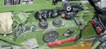
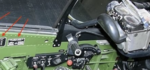
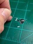
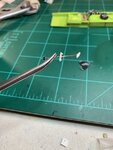
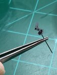
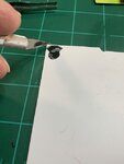
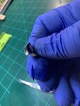
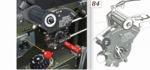
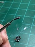
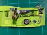
I'm currently working on the throttle quadrant.

As with almost everything else, I did a bit of research into finding what best represents the throttle body. It's nice to see pictures of the throttle with the rest of the interior, but I needed something that would help give me some close-up perspectives of the quadrant to help me determine the best approach to fabricating the body. I was fortunate to find a colored CGI & an artist's rendering from WW2Aircraft.net forum. This is a marvelous website and one can find a wealth of information. I highly recommend it.... :0)

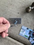
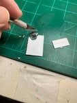
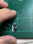
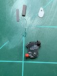
I have (now) dozens of photos of various stencils and accessories to choose from. I picked out the best of the three images that closely defined the size and detail.
 

Attachments

  • P-51 star gun mount # 1.png
    P-51 star gun mount # 1.png
    124 KB · Views: 50
  • P-51 throttl # 1AB.png
    P-51 throttl # 1AB.png
    40 KB · Views: 52
  • P-51 throttle # 1A.png
    P-51 throttle # 1A.png
    29.4 KB · Views: 51
  • P-51 throttl # 3.jpeg
    P-51 throttl # 3.jpeg
    65.9 KB · Views: 53
  • P-51 throttle # 2.jpeg
    P-51 throttle # 2.jpeg
    59.2 KB · Views: 53
Following the artist's rendering and close-up colored picture, I also made a stencil of the throttle lock mechanism. I used a small MicroMark punch-n-die to punch out the small circular tab. As this photo best illustrates, at such a small scale using only household tools and making everything from scratch without any photo-etchings or aftermarket sources, the punch-n-die route was the best way to go. I knew using a blade would simply pull the paper if I cut in such sharp curves and using a pair of scissors would only result in uneven circumference. I was lucky that I had a set that closely matches the diameter of the tab.
 

Attachments

  • P-51 throttle # 4.jpeg
    P-51 throttle # 4.jpeg
    111.2 KB · Views: 30
Here, I used a common pin as a shaft for the small handles to the locking mechanism. I also made a small stencil for the "T" handle itself, but I found at this small scale, it was too small to even see the details, let alone try to cut it to size and then glue to a small pice of plastic no bigger than a sliver. A lamp with a built-in lens really came in handy here.
 

Attachments

  • P-51 throttlr # 6.jpeg
    P-51 throttlr # 6.jpeg
    50.4 KB · Views: 29
  • P-51 throttle # 7.jpeg
    P-51 throttle # 7.jpeg
    53.2 KB · Views: 29
  • P-51 throttl # 8.jpeg
    P-51 throttl # 8.jpeg
    72.5 KB · Views: 29
I then hand-painted the small handles. The images all show the handles painted black. As with the star-shaped gun mount possibly being blended in with the rest of the green-colored zinc chromate as seen in my previous posts, in this case, I. opted for a bit of artistic license and painted them a dark gray. This way, they'll "pop out" a bit from the black throttle quadrant and give it a little bit more character.

At this point, I carefully placed the small pin and handles into a jar for safe keeping while I work on the throttle quadrant body. I felt such small delicate pieces would break off at the slightest mishandling and I didn't want to take any chances.

So this is where I am at the moment. All comments & suggestions are welcomed

Thank you for looking in.
 

Attachments

  • P-51 throttle # 10.jpeg
    P-51 throttle # 10.jpeg
    45.1 KB · Views: 35
Wurger,

Thank you, sir. Just to let you know that the Morava L-200 is one of the planes on my list. I owe it to you in your generosity in providing me with the drawings. I have alrready acquired some photos and videos of the L-200 in flight and during student training. Very interesting.
 
Good evening to everyone. The presidential election is in full swing. I already voted early last week to avoid the crowds and the potential virus.
Onto our subject tonight is the fabrication of the throttle quadrant body itself. From there, it was a simple matter of putting the quadrant body & all of the various components such as prop and mixture controls together.
I knew from previous postings and photos that the body itself has slots to accommodate the prop, throttle and mixture controls.
I also knew that the body was more than just wafer-thin shells laminated together to form slots. Thus, I added some filler to the body in between the slots.
This filler basically consisted of slightly thicker plastic sheet cut to (almost) the exact shape of the photo image and then laminated to the print. I added some body filler to the edges using a T-pin. Then I carefully sanded the edges down to the photo-image. My reasoning not to cut the plastic sheet all the way up to the exact size of the photo-image was I knew from past experience that sanding the hard plastic would affect the laminated soft photo paper. So, a somewhat soft filler was added to bring up the body to size.

From there I used a small brush and painted the edges black.
 

Attachments

  • P-51 throttle body # 1.jpeg
    P-51 throttle body # 1.jpeg
    30.2 KB · Views: 35
  • P-51 throttle body # 2.jpeg
    P-51 throttle body # 2.jpeg
    52.1 KB · Views: 32
  • P-51 throttle body # 3.jpeg
    P-51 throttle body # 3.jpeg
    52.8 KB · Views: 41
  • P-51 throttle body # 4.jpeg
    P-51 throttle body # 4.jpeg
    31.9 KB · Views: 34
  • P-51 throttle body # 5.jpeg
    P-51 throttle body # 5.jpeg
    37.4 KB · Views: 36
  • P-51 throttle body # 6.jpeg
    P-51 throttle body # 6.jpeg
    38.8 KB · Views: 36
Last edited:
Here, you can see how I laminated thin sheets of plastic behind the thicker plastic to form the body.
Unfortunately, I ended up making it too thick. As the last picture shows, the slots were so wide, I could almost drop a package in the mail.
So I recreated another body but used more thin laminations between shells and got better results.
Chalk that up as another learning experience.
 

Attachments

  • P-51 throttle body # 7.jpeg
    P-51 throttle body # 7.jpeg
    49.3 KB · Views: 35
  • P-51 throttle body # 8.jpeg
    P-51 throttle body # 8.jpeg
    41 KB · Views: 29
  • P-51 throttle body # 9.jpeg
    P-51 throttle body # 9.jpeg
    41.2 KB · Views: 30
Here, the mixture controls at the lower end and the prop control (black) were added. This is really the most easiest part as they basically consisted of pins with little balls on the ends. They were laminated to thin strips of plastic to simulate the "arm" to the controls. Then laminated inside the slots.

I thought using my hand as reference, would lend itself to scale and to the size I was working on. A lamp with a built-in lens really (again) proved useful here.
 

Attachments

  • P-51 throttle # 11.jpeg
    P-51 throttle # 11.jpeg
    57.8 KB · Views: 32
  • P-51 throttle # 12.jpeg
    P-51 throttle # 12.jpeg
    54.8 KB · Views: 31
Using the artist rendering and colored image of the throttle quadrant as my guide, I cut a small diameter hollow plastic tube to size.
I wanted to have a white "face" so I spray painted the tube with the end facing away from the spray. The paint covered the body itself but left the end alone.
I cut a small piece of wire to use as a mic button for the throttle. At the time, I only had red-colored wire that was of the size I needed, so I spray painted it black.
From there I threaded it through the tube to where the end stuck out of the "face."
I then pulled back the wire to a point where I felt it was sticking out just enough to be noticeable and pass for a "mic" on the throttle. Then I cut the back end off with a pair of dice cutters.
 

Attachments

  • P-51 throttle # 1A.png
    P-51 throttle # 1A.png
    29.4 KB · Views: 33
  • P-51 throttle # 20.jpeg
    P-51 throttle # 20.jpeg
    43 KB · Views: 40
  • P-51 throttle # 12A.jpeg
    P-51 throttle # 12A.jpeg
    36.5 KB · Views: 36
  • P-51 throttle # 13A.jpeg
    P-51 throttle # 13A.jpeg
    34.8 KB · Views: 32
  • P-51 throttle # 14A.jpeg
    P-51 throttle # 14A.jpeg
    36.8 KB · Views: 33
Using the previous artist rendering and colored image Ii could see that there was a cable attached to the throttle. My guess is that it's to connect the mic to the radio permitting the pilot to communicate.
I cut up small bits and pieces to help fabricate what I thought would pass for a "clip" holding the cable to the throttle.
 

Attachments

  • P-51 throttle  # 15A.jpeg
    P-51 throttle # 15A.jpeg
    62.4 KB · Views: 35
  • P-51 throttle # 16A.jpeg
    P-51 throttle # 16A.jpeg
    43.9 KB · Views: 34
  • P-51 throttle # 17A.jpeg
    P-51 throttle # 17A.jpeg
    44.9 KB · Views: 32
Remember my previous post # 564? I then compressed all of the small bits together to form the throttle lock controls. When you look at it here, It appears very small.......
 

Attachments

  • P-51 throttle # 14.jpeg
    P-51 throttle # 14.jpeg
    47.2 KB · Views: 32
But when you look as it truly appears in my hand, it becomes almost ridiculously tiny. My eyes crossed over a couple of times here.....
 

Attachments

  • P-51 throttle # 15.jpeg
    P-51 throttle # 15.jpeg
    51.1 KB · Views: 28
The (ridiculously) tiny throttle locking controls were then glued into place on the throttle quadrant body along with the wire.
 

Attachments

  • P-51 throttle # 13.jpeg
    P-51 throttle # 13.jpeg
    49.2 KB · Views: 37
This is the left side panel as it stands today. I have not permanently attached the throttle quadrant because I feel it's too fragile and because of its location near the top edge of the left side panel, it would be very easy for me to knock it off during covering of the fuselage with metal foil. So, it'll be added on almost at the very end.

Thank you all, for looking in.
Gary
 

Attachments

  • P-51 throttle # 19.jpeg
    P-51 throttle # 19.jpeg
    58.7 KB · Views: 37

Users who are viewing this thread

Back