Super detailing Guillow's P-51D Mustang

Ad: This forum contains affiliate links to products on Amazon and eBay. More information in Terms and rules

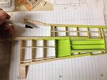
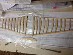
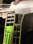
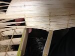
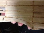
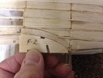
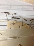
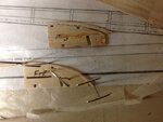
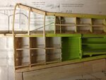
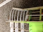
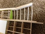
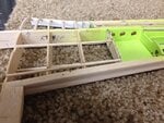
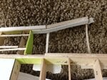
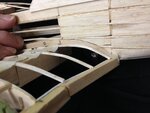
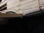
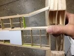
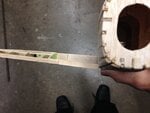
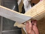
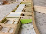
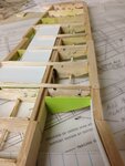
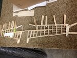
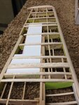
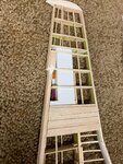
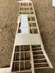
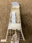
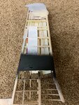
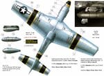
Not to say I haven't been busy working on the model. I have made slow progress, mostly in fine-tuning & smoothing out the ailerons, flaps & sections of the wings. Will resume posting shortly. Thank you for your patience. Skye
 
Good day to one and all. I've been working on several parts of the Mustang. While one portion was being dried, I would transfer to some other section and try to accomplish some work there and so on. I must admit that I had to revisit my site a couple of times to help bring myself "up to date" and not start repeating myself. To wit: I left off with the question of trying to have a super detailed wheel well.

I apologize in advance for bringing up the first picture again, but it's worth noting where I stood before. I was trying to figure out a way to continue with the construction of the wing and at the same time, allow room for the wheel well. It was definitely not part of the Guillow's design. Looking at the second and third photos, one can easily see that the wing opening is readily apparent and leaves much room for the wheel well areas. The second picture also shows how wide open the gap is.

As the last picture shows, Guillow's kit calls for the wing to be constructed using solid 1/16" (sorry about the English measurements, guys) balsa wood. Definitely no room for the wheel well areas. On that note, I also pondered on how to continue with the wing up to the root section and still have a strong and rigid framework by which the model can stand.
 

Attachments

  • P-51 wheel well & wing outlines # 28.JPG
    P-51 wheel well & wing outlines # 28.JPG
    227.8 KB · Views: 68
  • P-51 wheel well & wing outlines # 29.JPG
    P-51 wheel well & wing outlines # 29.JPG
    222 KB · Views: 67
  • P-51 wheel well & wing outlines # 30.jpg
    P-51 wheel well & wing outlines # 30.jpg
    36.7 KB · Views: 71
  • Mustang model # 2.JPG
    Mustang model # 2.JPG
    53.5 KB · Views: 74
As the first picture shows, Guillow's plans call for solid ribs throughout the wing construction.I

I needed a way to find a solution to the dilemma of continuing the wing construction that will maintain the correct airfoil shape, and just as importantly, the correct size, of the wing chord and its thickness and at the same time, allow room for the wheel wells. That's when I hit upon an idea of using laminations of thin strips of balsa wood. But how to maintain the correct airfoil shape such that it will also fit within the fuselage saddle?
 

Attachments

  • Guillow's Instructions 2.jpg
    Guillow's Instructions 2.jpg
    58 KB · Views: 69
  • P-51 wheel well & wing outlines # 16A.jpg
    P-51 wheel well & wing outlines # 16A.jpg
    49.2 KB · Views: 63
  • P-51 wheel well & wing outlines # 17A.jpg
    P-51 wheel well & wing outlines # 17A.jpg
    46.4 KB · Views: 57
  • P-51 wheel well & wing outlines # 18.JPG
    P-51 wheel well & wing outlines # 18.JPG
    212.3 KB · Views: 63
Last edited:
That is when the opportunity and a bit of imagination combined to offer a solution that was literally right in front of me. Why not use the very same balsa ribs supplied in the kit as templates to fit the laminated strips of balsa into the fuselage saddle? I could also use the succeeding ribs to help keep the correct wing taper and thickness all the way down to where the solid ribs began. Thus, I could now maintain the correct sized "ribs" that will provide me with the matching curvature of the wing along with the fit into the fuselage saddle. The last picture shows the laminations only positioned onto the wing. I will have to cut and trim the ribs to correctly fit within the main spar and the leading edge. I also knew that just three laminated "false" ribs would not be sufficient to maintain the strength needed to withstand the stress as well as helping to maintain the correct profile of the wing.
 

Attachments

  • P-51 wheel well & wing outlines # 19A.jpg
    P-51 wheel well & wing outlines # 19A.jpg
    43.3 KB · Views: 58
  • P-51 wheel well & wing outlines # 21A.jpg
    P-51 wheel well & wing outlines # 21A.jpg
    41.1 KB · Views: 54
  • P-51 wheel well & wing outlines # 22A.jpg
    P-51 wheel well & wing outlines # 22A.jpg
    45.4 KB · Views: 59
  • P-51 wheel well & wing outlines # 23A.jpg
    P-51 wheel well & wing outlines # 23A.jpg
    55.3 KB · Views: 65
Using a bit of extrapolation combined with some eyeballing, I reproduced several additional "falsa" ribs to fit between the laminations. Pretty nifty, eh?

The last photo shows it edged-on and best illustrates my effort maintaining the constant wing taper as it flows out toward the wing tip. So, its really a three-dimensional effort here.
 

Attachments

  • P-51 wheel well & wing outlines # 47A.jpg
    P-51 wheel well & wing outlines # 47A.jpg
    77.3 KB · Views: 56
  • P-51 wheel well & wing outlines # 5A.jpg
    P-51 wheel well & wing outlines # 5A.jpg
    373.8 KB · Views: 53
  • P-51 wheel well & wing outlines # 6B.jpg
    P-51 wheel well & wing outlines # 6B.jpg
    83.2 KB · Views: 54
Last edited:
Thank you Wurger, sir. I'm still 'kicking" up the model, just a bit slower as it really is being built.
 
A temporary fitting of the first two laminated false ribs as viewed from the underside of the wing validates the room needed for the wheel well area detailing.

Next, a fitting to the fuselage saddle verifies the use of the Guillow's ribs as templates. it wasn't all that easy and smooth. I had to do a little bit of "fudging" and sanding on the wing and fuselage saddle to get them to fit close together.

A bit of a close up of the leading edge of the wing to the fuselage. Note that it is positioned low. This is normal as I understand it from all the drawings and 3-views I've seen. The leading edge has not been sanded round at this point. Nor have the rest of the false ribs been permanently glued in place or sanded smooth. That small piece of paper is used to help minimize further dents into the fuselage as evident from my previous fittings. It's fit, sand, cut, repeat process .....

A photo of a plastic model taken -with permission to print here, from Scale Aircraft Modelers- shows how the leading edge of the wing is low relative to the fuselage.
 

Attachments

  • P-51 wheel well & wing outlines # 45.JPG
    P-51 wheel well & wing outlines # 45.JPG
    377.5 KB · Views: 70
  • P-51 wheel well & wing outlines # 42.JPG
    P-51 wheel well & wing outlines # 42.JPG
    180 KB · Views: 69
  • P-51 wheel well & wing outlines # 43.JPG
    P-51 wheel well & wing outlines # 43.JPG
    126.1 KB · Views: 73
  • P-51 wheel well & wing outlines # 50.JPG
    P-51 wheel well & wing outlines # 50.JPG
    321.7 KB · Views: 75
Next on the agenda was dealing with the Guilllow's flat bottomed wing. It was originally designed for rubber power and later years, small electic motors. However, the airfoil used is definitely Clark Y at its best. The first two pictures show the wing and its undersides. From this perspective, it really doesn't look too bad. That is, until one temporarily covers the undrside with a piece of paper.

The third photo shows just how flat that wing truly is. The fuselage nose to to the right of this photo.
 

Attachments

  • P-51 wheel well & wing outlines # 29.JPG
    P-51 wheel well & wing outlines # 29.JPG
    222 KB · Views: 51
  • P-51 wheel well & wing outlines # 30A.jpg
    P-51 wheel well & wing outlines # 30A.jpg
    36.7 KB · Views: 63
  • P-51 wheel well  wing outlines # 28A.jpg
    P-51 wheel well wing outlines # 28A.jpg
    52.7 KB · Views: 67
For those who might be interested to know, while reviewing my previous posts, I've added a third photo to my post # 65 to illustrate the wing taper.
 
Moving forward, To deal with the flat bottomed wing, I've added some strips of balsa to the underside of the solid balsa ribs. This photo shows only the balsa strips being placed down prior to gluing. I've always tried to follow my own mantra of "trial fitting before gluing." It may add an extra step and definitely slows down the building process, but I'm treading into new territory here and it seems to work best for me. You wouldn't believe how many potential mistakes I've managed to avoid by allowing for a trial fit before gluing. Even then, despite my best intentions, mistakes happen. In this picture, it also shows that my initial intentions was simply to glue them over the ribs and sand the front and rear ends down to blend with the leading and trailing edges of the wing. As you can see, it wasn't going to work too well. Thus, I knew I would have a llittle bit more work to do and would also have to beef up at least the leading edges.

The second photo shows me only using a small section of the balsa wood to determine whether or not this would be a good fit. When taking into account for sanding down the front edges of the added strips, it was a good choice.

I started out by using clothes pins to clamp down the added leading edge strips for an even surface between laminations.
 

Attachments

  • P-51 wheel well & wing outlines # 31.JPG
    P-51 wheel well & wing outlines # 31.JPG
    209 KB · Views: 58
  • P-51 wheel well & wing outlines # 32.JPG
    P-51 wheel well & wing outlines # 32.JPG
    232.5 KB · Views: 55
  • P-51 wheel well & wing outlines # 39.JPG
    P-51 wheel well & wing outlines # 39.JPG
    331.9 KB · Views: 54
As you can see, the results speak for themselves. That one sectrion where I added extra wide strips of balsa was to take into account for the machine gun ejector chutes cutouts from the underside of the wing. As further examination turned out, it wasn't enough. The spread of the ejector chutes were too widely spaced apart, so I added more strips to this area. I'm al;so taking into consideration, should I be obsessed enough to add drop tanks, the extra efforts and wood will help here. You might be asking if I'm just going to add some cutouts to the underside skin, why the extra wood? Ah, glad you asked.
 

Attachments

  • P-51 wheel well & underside # 1.JPG
    P-51 wheel well & underside # 1.JPG
    264.8 KB · Views: 49
As the following photos show: I've added the extra strips of balsa. Sanded them down to blend in with the leading and trailing edges of the wing. There were still some uneven strips so I added Spackling Compound as filler. This is used on dry wall applications on building or remodeling a house and is widely available at hardware stores. It goes on pink colored, but when its completely dried, it's white colored to let one know that it's ready for sanding. It is extremely easy to sand and much softer than balsa, which helps to minimize the accidental sanding of the surrounding balsa woods. Only issue, is to make sure the sanding is done in a well ventilated area or outside. The extra fine dust can be an irritant to the skins and can be easily breathed in.

When all is sanded and wiped down with a damp cloth and let to completely dry, it's ready for paint. A flat black was used here.
 

Attachments

  • P-51 wing undersides # `.jpg
    P-51 wing undersides # `.jpg
    717.2 KB · Views: 62
  • P-51 wing undersides # 2.jpg
    P-51 wing undersides # 2.jpg
    756.3 KB · Views: 66
  • P-51 wing, underside view before black paint # 1.jpg
    P-51 wing, underside view before black paint # 1.jpg
    732 KB · Views: 65
  • P-51 wing undersides black paint # 1.jpg
    P-51 wing undersides black paint # 1.jpg
    774.7 KB · Views: 61
As this illustration will show, the ejector chutes are widely spaced apart with the possible drop tank shackle in between. It also shows that the cutouts to the ejector chutes are black. Or more accurately,the internal chutes cannot easily be seen. Thus, when I cover the underside of the wing with my "skin" and I cut out the rectangular openings for the ejector chutes, the background should be black. Lots of thinking done here, gentlemen. Just hoping it all works out.
 

Attachments

  • P-51D # 2 stencils.jpg
    P-51D # 2 stencils.jpg
    1.1 MB · Views: 68
Crimea and Wurger,

Thank you gentlemen. Perhaps all this thinking might explain why my wife said to me last week, "Hey, you just missed the turn out to my aunt's house. Now we'll have to turn around and go back. What were you thinking?" Hmmmmmm
 

Users who are viewing this thread

Back