Super Detailing S.E.5 Guillow's model

Ad: This forum contains affiliate links to products on Amazon and eBay. More information in Terms and rules

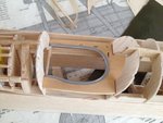
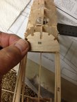
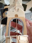
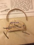
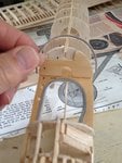
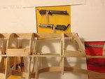
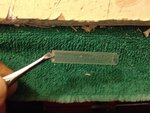
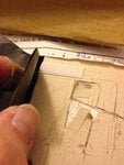
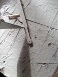
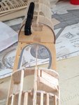
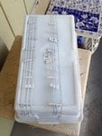
This the second piece. It was then glued into place. I also cut out small openings for the throttle controls. Note that I had the mid-level basswood "tongue" stick into the opening of the former used as an instrument panel. Very nice and clean at this point. It pays to practice first on scrap pieces.
 

Attachments

  • SE5 31.JPG
    SE5 31.JPG
    261.1 KB · Views: 56
This piece will serve as a template for the instrument panel and also for the laminated interior support structures. It will eventually be cut away.
 

Attachments

  • SE5 246.jpg
    SE5 246.jpg
    202.1 KB · Views: 46
This balsa piece is now temporarily in place to determine the correct size for lamination of 1/32 lite ply. Notice how I made the "template" smaller than the back former. This is to take into consideration of the laminated woods. I chose wood for the thin structural support because in the previous b+w photo of the "parlor" picture, one can see the small vertical curved supports made of wood as well. Lite ply was chosen because its very strong for its thickness and because it's only 1/32' thick, will be very easy to bend to shape.
 

Attachments

  • SE5 62.JPG
    SE5 62.JPG
    220.6 KB · Views: 48
I then made the instrument panel also out of basswood. Note the unfinished basswood for the instrument panel and the stained finish of the basswood used as mid-level support. Compare this basswood cut out for the instrument panel with the colored photo.
 

Attachments

  • SE5 34.JPG
    SE5 34.JPG
    257.6 KB · Views: 59
  • SE5 29.jpg
    SE5 29.jpg
    179.5 KB · Views: 58
The lower wing was also constructed and fitted to the fuselage. This was done at this stage to test-fit the wing saddle to the lower wing and if any changes needed to be made, this would be a good time. Otherwise, I may end up cutting through all of the cockpit detailing and I wanted to avoid that.
 

Attachments

  • SE5 45.JPG
    SE5 45.JPG
    161 KB · Views: 57
  • SE5 46.JPG
    SE5 46.JPG
    245.8 KB · Views: 62
The lite ply lamination process. Then the results were test-fitted over what will be the instrument panel. The balsa wood former will eventually be cut away leaving the basswood instrument panel and the lamination for support to the front cover over the cockpit.
 

Attachments

  • SE5 63.JPG
    SE5 63.JPG
    199.5 KB · Views: 48
  • SE5 64.JPG
    SE5 64.JPG
    241.2 KB · Views: 48
  • SE5 49.JPG
    SE5 49.JPG
    254 KB · Views: 50
  • SE5 50.JPG
    SE5 50.JPG
    226.7 KB · Views: 54
The next item on my agenda is the Vickers machine gun. Since there were no Vickers (or Lewis) machine guns available in my scale, I had to fabricate one from scratch. Therefore, I chose to fabricate the machine gun first before the instrument dials because it is a major component of the cockpit interior and I needed it to fit properly. Its easier to (slightly) enlarge or reduce the dials than to adjust the size and cut outs for the machine gun or even the machine gun itself.

To start: I used an advertisement to help me get the details I needed for the gun. It was decided not to go fully into detailing the gun as most of it will be hidden inside the cockpit and under the top decking anyway. Still, it will be nice to practice fabricating the Vickers gun as I know I'll have to fabricate a Lewis machine gun and that will be sitting on the top wing for everyone to see. I used a small piece of plastic tubing that I found around my stash box to use as the main barrel.
 

Attachments

  • SE5 33.jpg
    SE5 33.jpg
    216.6 KB · Views: 52
  • SE5 35.jpg
    SE5 35.jpg
    255.5 KB · Views: 54
To simulate the corrugated cooling portion of the barrel, I used Evergreen half-round strips of plastic. They were also used to simulate the rigging. At that time, I didn't know about Vape metal strips and wished I had used those instead of the plasticstrut. Oh well, lessons learned.

I then cut another thin strip from the black electrical tape and wrapped both ends of the barrel.

Laying down the plastic "barrel" next to the strips, I then cut a series of strips to fit within the length of the barrel between the two strips of tape.
 

Attachments

  • SE5 48.JPG
    SE5 48.JPG
    189.2 KB · Views: 46
  • SE5 47.JPG
    SE5 47.JPG
    239.4 KB · Views: 46
  • SE5 36.JPG
    SE5 36.JPG
    228.5 KB · Views: 53
  • SE5 37.JPG
    SE5 37.JPG
    277.2 KB · Views: 50
The strips of plastic were then laid side-by-side and cut to ensure all were the same length. Then each strip was glued onto the barrel.
 

Attachments

  • SE5 38.JPG
    SE5 38.JPG
    264.4 KB · Views: 41
  • SE5 39.JPG
    SE5 39.JPG
    351.6 KB · Views: 46
The front nozzle to the front of the machine gun was fabricated from a piece of Evergreen tubing that was cut to size. The end was drilled out using a pin vise and then sanded round using sand paper.
 

Attachments

  • SE5 40.JPG
    SE5 40.JPG
    304.2 KB · Views: 41
  • IMG_5323.JPG
    IMG_5323.JPG
    47.3 KB · Views: 41
As can be seen, the barrel is shaping up very nicely.
 

Attachments

  • SE5 44.JPG
    SE5 44.JPG
    226.5 KB · Views: 61
  • SE5 41.JPG
    SE5 41.JPG
    237.9 KB · Views: 66
Next came the breech to the machine gun and some of the charging handles. Balsa wood was used as the base or foundation. I also used Evergreen plastic sheet and "punch" out some rivets using a dull needle and small hammer on the backside. This sheet of plastic was then wrapped around the balsa wood. This is far easier than sanding, filling up the wood grain with filler, sanding some more, then adding primer to seal the filler and then sanding more...... You get the idea. Using plastic saved me a lot of work.

The charging handles and other little "goodies" were fabricated from scrap pieces of plastic found laying around.
 

Attachments

  • SE5 42.JPG
    SE5 42.JPG
    267.5 KB · Views: 46
  • SE5 25.jpg
    SE5 25.jpg
    22.7 KB · Views: 60
  • SE5 26.jpg
    SE5 26.jpg
    37.1 KB · Views: 49
  • SE5 43.jpg
    SE5 43.jpg
    279.8 KB · Views: 56
The machine gun was then given a light coat of glossy black spray paint. Then I lightly dusted the details using a paint brush dipped in silver paint and run over a piece of paper until almost all of the paint was rubbed off the brush. The brush was then lightly brushed over the details. In the modeling world, this is called "Picking out the highlights."
 

Attachments

  • SE5 27.jpg
    SE5 27.jpg
    34.6 KB · Views: 59
The basswood instrument panel is now stained with the same light "peach pecan" wood stain as the mid-level support. The lamination of plywood is now glued in place over the instrument panel. The next picture shows the back balsa wood former cut away,
 

Attachments

  • SE5 50.JPG
    SE5 50.JPG
    226.7 KB · Views: 50
  • SE5 54.JPG
    SE5 54.JPG
    245.6 KB · Views: 52
The Vickers machine gun is only test-fitted in place to check all fittings and cutouts. It is also tested for correct side elevation. As can be seen, the second former also had to be cut away to allow the barrel to rest. The cut was gradually made such that the side elevation was correct and the necessary clearances for the cover was made.
 

Attachments

  • SE5 55.JPG
    SE5 55.JPG
    206.2 KB · Views: 47
  • SE5 56.JPG
    SE5 56.JPG
    236.9 KB · Views: 51
Last edited:
Great! I like the way you made the MG. Well done. :thumbright:
 
Next came the faces to the instruments. Referring to the colored photograph, each instrument dial was made by cutting out circles from black paper easily purchased from the local arts and crafts store. The black electrical tape was painted white. I tried using "White Out" tape, but it turned out to be very difficult to trace into a circle without sticking onto the paper or tearing. The electrical tape was suspended over small balsa blocks during the painting to prevent any paint from spreading out over the edges. Each tape was then carefully removed and cut to various lengths. The last picture shows both the large size of the dials and my approach to making the faces. These large sizes allows me to see how each face will be finished and will eventually be reduced to scale.
 

Attachments

  • SE5 29.jpg
    SE5 29.jpg
    179.5 KB · Views: 64
  • SE5 65.JPG
    SE5 65.JPG
    286.1 KB · Views: 66
  • SE5 66.JPG
    SE5 66.JPG
    239.7 KB · Views: 65
  • SE5 67.JPG
    SE5 67.JPG
    284.3 KB · Views: 59
Each dial was custom-made to resemble the actual instrument as close as possible. The S.E.5 was unique in that most, if not all, of the instruments were specific to that particular aircraft.
 

Attachments

  • SE5 69.JPG
    SE5 69.JPG
    378.3 KB · Views: 52
At the time, my scanner did not have the ability to reduce the photos of dials. No problem. I simply used my old colored film camera and took a guess at the distance to take pictures of the dials. As you can see, the first picture, I was just a bit too close. The next picture shows the dials more closely to scale that I wanted. I had the films developed into pictures and simply cut them out.

**Very special note: we had a "butcher block" patterned kitchen counter top. This will come very handy later on during the build. Ahh, nooo, I'm not going to cut up the kitchen counter top. LoL
 

Attachments

  • SE5 68.JPG
    SE5 68.JPG
    230.3 KB · Views: 52
  • SE5 70.JPG
    SE5 70.JPG
    241.1 KB · Views: 50
To make the lens for each dial, I used a simple "punch & die" set obtained from a local hardware store. I also used the same punch & die set to "punch" out the small brass circles for the base of each dial. The instrument bezels were from rings easily obtained from local arts and crafts stores. These rings can be in natural silver, brass, copper, and black. I chose a variety of rings to suit my needs.
 

Attachments

  • SE5 73.JPG
    SE5 73.JPG
    226.7 KB · Views: 47
  • P-51 # 99.JPG
    P-51 # 99.JPG
    323.5 KB · Views: 52
  • SE5 4.jpg
    SE5 4.jpg
    29.8 KB · Views: 55

Users who are viewing this thread

Back