1/24 ME 109 E-4

Ad: This forum contains affiliate links to products on Amazon and eBay. More information in Terms and rules

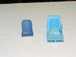
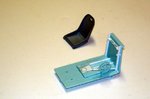
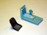
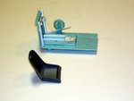
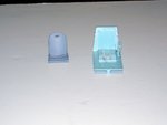
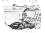
Well thank you guys .Now thats what I mean about artist pics.The first seat with the Japanese writing is more realistic to the pics while the 2nd one(my example) shows that taper and the shape is wrong.The seat is scalloped in the back with a pocket for the bottom like the pics and that 1st drawing.Thanks for the info on the lines and Terry the IP did not remind me of a G but might need to look again.Oh yea no dog gone Revi c/12 gunsight not hard to build made one for the G6 out of 11 pieces just a bit time consuming.Glenn that kinda crossed my mind ;) 38D's sre for the bedroom.
 
Nice pics Wojtek, and interesting the the (presumably) Swiss 'emil' has a Hurricane - type control column grip !
I tried moulding a seat, which worked to an extent, but with all the compound curves and the 'dish' in the seat pan and back, it was difficult to get it right as a one piece moulding. I'm probably going to mould the pan and back separately, then blend them together with Milliput, using copper or brass wire to make the rolled edges.
 
Teryy I used on my 2nd seat(scrap now :lol:) some very thin factory evergreen for the roll and looks pretty convining I think you start to make it out in the last two pics.
 

Attachments

  • bandai 004_edited (900 x 674).jpg
    bandai 004_edited (900 x 674).jpg
    31.7 KB · Views: 140
  • bandai 006_edited (900 x 673).jpg
    bandai 006_edited (900 x 673).jpg
    42.9 KB · Views: 147
  • bandai 008_edited (900 x 673).jpg
    bandai 008_edited (900 x 673).jpg
    46.1 KB · Views: 167
Yep, I can see it Kevin. The rolled edge isn't a problem, it's getting an accurate, 'rounded' shape to the overall seat as a single moulding - a bit beyond the limitations of heat moulding unfortunately. I have a plan though, maybe not a cunning plan, but a plan anyway .......
 
As I said...a wooden former and a styrene plate wormed up and stretched on the former.The rolled edge - brassy wire.
 
I've tried it Wojtek, but as mentioned above, it's difficult to obtain the correct shape overall, due to the curve of the seat back and pan. I'm going to try again, but make two separate wooden moulds, then join and blend the parts together.
 
I made my former out of milliput and still I had little sucees I tried 3X but hey this is my first rodeo with that techique so.....But I did finally get a seat made with a curve and as it approaching the looks of the pic at lets say 80% and that was after 3X tries on that method.So after 4-5 attempts I have something I thing I am going to use;I will make that call after the paint has been applied.I also made the brace for the R/S of fuse that holds 3X T/handles along with 5X T/handles 2 being for the IP and the long bar handle w/ball for the L/S of IP
 
Nice job on the seat there Wojtek ;) .I have some pics of my efforts on the pit thus far.I used the the more rounded seat(drawing) from Wojteks pics along with the actual's.This pit is so barren it screams for detail and I am enjoying it for the time being.It's kinda like some of the old Revell kits with little of nothing so no grinding just make and place.If you notice I nade the pulley on the L/S of seat out of 2X small disc from the Wadron hole punch kit.I would imagine that it was used to raise and lower the seat for the pilots desired height.I would guess guys that the tank on the R/S is O2?anyone have a pic of the tank outside the holder?
 

Attachments

  • ban1_edited (900 x 673).jpg
    ban1_edited (900 x 673).jpg
    50.5 KB · Views: 99
  • ban4_edited (900 x 589).jpg
    ban4_edited (900 x 589).jpg
    57.6 KB · Views: 93
  • ban5_edited (900 x 674).jpg
    ban5_edited (900 x 674).jpg
    71.6 KB · Views: 135
  • ban6_edited (900 x 674).jpg
    ban6_edited (900 x 674).jpg
    67.6 KB · Views: 124
  • ban2_edited (900 x 675).jpg
    ban2_edited (900 x 675).jpg
    39.9 KB · Views: 127
Looking really great Kev.... :thumbright:

Concerning these two small disks ( circles) . As memo serves these were for flap adjustment ( the outboard one) and the horizontal stabilizer adjustment ( the inboard one). For the seat adjustment was the lever next to these circles.
 
The hand wheels were for the tailplane incidence adjustment, with a small indicator below and foreward of it, and for the emergency lowering of the landing gear. A chain drive runs back horizontally for the tailplane adjuster, and another at approximately 45 degrees and forward for the U/C lowering.
The oxygen filter and regulator unit was on the starboard side, at floor level, covered by an anodised metal plate with a series of perforations, as shown in the drawings and pics Wojtek posted.
Good work so far Kevin, especially on the seat.
 
Thks Wojtek and Terry.I made #5 for the R/S of pit and it has to go there otherwise it hits the trim wheel but I am interested in #12?It looks like the handle bolts into #5 then works a rod and lever off of #12 is that right?I have #7,8,9 in place.A little chain for the trim wheel something I will use from 1/700 scale ships works well in making your own chain acouple more dodads and the R/S is done.Terry the IP is the Emil setup and actually a very good repo something they got right.Got to shower went pedaling for awhile.Cheers Kevin ;)
 
Ah, now I understand !
The item at No.12 is the tailplane incidence indicator, and is nowhere near the handle at No.11.
The incidence indicator is like a small bubble level, with a '+' and '-' mark fore and aft, and shows the angle of the tailplane, which could be adjusted in angle of attack by the round pulley wheel. The handle at No. 11 is the seat height adjuster.
I should have a clear pic and drawing of the incidence indicator, which is mounted on the lower port wall, which I'll post here later.
NOTE. The incidence indicator appears to be missing in the colour pic with the transparent fuselage section, and also, the throttle lever handle is non-standard for the 'E' version, being more like the 'F' series onwards. On the 'E', it was normally a 'ball' type handle, yellow (for fuel) with a thin red stripe running centrally fore and aft.
 
Last edited:
I would appreciate that Terry but does the handle from #5 become a part of #12 ? About 1/2 way up handle #5 it looks like a wingnut going into #12?
 
No, Number 12, the incidence indicator, is a separate, small casting, enclosing the bubble level. The wing nut you mention is the friction adjuster on the lever, No.4. This quadrant, enclosing throttle, pitch and mixture, is above the indicator, it's jsut the angle of the drawing (obviously produced as a line drawing from a photo) making it look all one item.
I'll go and find the drawing and scan and post it, then it should all be clear. Back soon !
 
Here's the drawing mentioned in my last post. I have a good, clear colour pic also, but it's one of a group I've been asked not to publish. But I can confirm it looks exactly the same in the pic and the drawing.
Note that on the E1, E3 and earlier E4s, the throttle lever had the ball grip as described, and shown in the drawing provided by Wojtek. Later E4s and E7s had the larger grip, incorporating the prop pitch control, the small thumb switch on the end of the grip. Those aircraft with the ball grip had the pitch control as a vertically mounted lever type of switch, centrally positioned on the lower part of the main instrument panel, between the turn bank indicator and the rev counter.
The incidence indicator casting was often bare metal, but also very often the same interior colour, with the 'bubble' window looking yellowish, just as on a spirit level.
Hope this helps.
 

Attachments

  • Can Jan 384.jpg
    Can Jan 384.jpg
    72.4 KB · Views: 107
So another question Terry as we look at the Throttle control the hump is backwards to the other drawings is this correct something they did for the E4-7 and it appears to maybe have two lever arms inside?Thaks this is helping Thks alot .
 
Last edited:

Users who are viewing this thread

Back