1:32 scale Lancaster Mk.1 Hachette Partworks

Ad: This forum contains affiliate links to products on Amazon and eBay. More information in Terms and rules

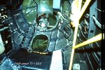
Didn't say it wasn't worth displaying it Ian, just that in normal operational use, it wouldn't be in the astrodome until required.
It's up to Gerry, but personally, I think it would possibly obstruct the view, through the dome, into the W/Op's position which, in this scale, should be viewable from above.
 
Thanks Gnomey, David, Martin, Terry, Andy, Wayne, Ian, Wurger, Jan and George for your most recent contributions to this topic. And welcome B29WereWolf.

Ian, I hadn't thought about the astro compass. It's not a part that comes with the series. I would need to dig out some references as to what it looks like - particularly in the astrodome. I've a feeling I've seen some shots of it in the background, on a shelf directly behind the navigator's seat?

Terry, thanks again for your offer of references. I think Andy may already have gazumped you with the latest pictures he posted. I have a question on Andy's picture showing the bomb sight in the blister. The two large V-shaped brackets on either side of the sight, what was the purpose of these? They don't always appear to be present in other references I have. Were they an additional support for the bomb sight mount and were they angled slightly forward into the blister or backwards into the compartment? The magazine instructions show them very prominently protruding into the blister but I can't find any references that show them as visible on actual aircraft.

Finally, George - that penny. That's all I have left after buying this series!

Sláinte,

Gerry
 
Last edited:
Hi Gerry,

I don't think fitting the compass would hide other detail seeing as you can look directly through the fuselage ribs!
so fitting the compass would be a nice addition to detailing the inside of the astra-dome/canopy,Don't forget there
was also a curtain/sunshade fitted the inside of the main canopy, usually seen folded back though, Anyway....

What the compass looks like.


View: https://www.youtube.com/watch?v=1O54J3CDvyE
 
The brackets were in place on all wartime Lancs Gerry, with the possible exception of those fitted with the SABS equipment, and protrude slightly forward, into the blister.
Although I have never been able to establish an exact purpose for them, I've been told by Lanc crew members that they were originally for a bomb sight mount (although these were actually mounted on brackets on the floor frames), as well as supports and 'hand grips' for the bomb aimer during violent manouvres, and could also act as a step when entering or exiting the front turret.
In the photo of the BBMF Lanc below, taken in 1983, the brackets are visible, although the starboard one is partly hidden by the turret ammo can, and you can see that the later bomb sight mounting bracket, on the floor, is also attached, by vertical bars, to the inner end of the brackets. At left in the photo is the bomb sight computer.
Apologies for the poor quality of the photo - it was scanned from one of my original (rejected) 35mm 'Ektachrome' transparencies !
 

Attachments

  • 2011-04-11_13.JPG
    2011-04-11_13.JPG
    116.1 KB · Views: 125
Hi Gerry. I hope I didn't confuse you with that pic. Here's another from outside to show how far the frame protruded into the nose on the CWH Lanc.

Nose.jpg
 
Thanks Darryl, Bill and David and thanks Terry for your further information on the brackets. Your knowledge on this, and most other aviation subjects, is encyclopedic. That's why I enjoy posting to this forum so much. Andy, thanks for that profile photo, the brackets are hardly visible. That's Andy:1, Magazine: 0!

Thanks for that video Ian. Excellent references of the compass and case if I get to include it.


Cheers,

Gerry
 
Gerry, I'll be able to cosy up to the Nanton Lancaster again this weekend so if you need more pics, just holler. Not sure if the bomb aimer's position will be accessible but I can try.
 
Andy, Thanks for the offer but I don't have any other specific questions at the moment. Am progressing the painting of the consoles at the moment and should have some pictures to post in the next few days.

Gerry
 
Well Guys, I would certainly love to have a Lanc within visiting distance too. It would sure save me a lot of head scratching, at times! But, as promised, here are some shots of the latest detail painting.

First I decided to do a little extra scratch-building, as every time I look at my reference shots I seem to see something new. These are two oxygen economisers, for the navigator and radio operator and an astro compass, all made from scrap wood, plastic rod and card. The astro compass is very different from the refs that Ian posted but is identified as such in the SAM Lancaster manual on Page 118, photo 13. This is the equipment I'd seen before, behind the navigator, on the s/board fuselage.

Astrocompasswood_zps18059245.jpg


Astrocompasspainted_zps522459de.jpg


The second photo shows these painted up with a couple of extra additions. (A) is a pump that sits on the port fuselage just behind the pilot's seat. (B) The oxygen economisers with some hoses added with 1mm lead wire. The underside of one still needs to be painted. (C) The astro compass - a later version, perhaps? (D) is an extra panel for the bomb aimer's compartment, portside beside the blister.

Paintedcamera_zpsac44c0a4.jpg


This is the camera stand assembled, painted and weathered with some placards and cable added. Also the step/tank.

Paintedconsoles_zpsf313151a.jpg


Here are the bomb aimer's consoles. (A) for the port side. The wedges under the computer is to position it over a former. (B) are the selection panels for the s/board side. The cables are painted lead wire, to be teased into position, when installed.

Paintedbombaimersbulkhead_zpse9dcb5eb.jpg


This is how the bulkhead should fit together when positioned. I've already discovered that it will probably need some tweaking to fit properly inside the nose section. I'm trying to decide whether it would be easier to attach some of the fittings to the panels before installation. I guess I'll just have to experiment to find the best method. I might not be able to get so clear a photo when it's installed.

Paintedbombsight_zps65b967c9.jpg


Finally, in this section, the bomb sight. Not too much to say about that really.

Paintedtrimwheels_zps40ed2ded.jpg


Back to the pilot's cabin and this is the trim wheel assembly, to the right of the pilot's seat.

Paintedhandrail_zps656f2519.jpg


And lastly, some other pieces painted. The guide rail, the bomb aimers rest and three overhead cabin lights for other parts of the fuselage.

That's it for now, The fun part begins, fitting them all in position next. That should keep me going for a while! Will keep you updated on progress.

Cheers,

Gerry
 
Stunning work Gerry. I took a quick peek into the Nanton Lanc and it turns out that there's not much installed in the bomb aimer's position yet, being a work in progress.
 
Beautiful work Gerry.
That 'astro compass' is,I believe, a drift sight, not a compass, and is fixed to the starboard wall, viewing via a port in the fuselage skin, or, by unlatching it and going forward into the bomb aimer's compartment, it could then be attached to a fitting on those two brackets we mentioned earlier, and the sightings taken through the flat panel in the floor. It was essential to have the sight 'fixed', in order to obtain an accurate reading of drift in relation to the sighting point.
It was used for assessing drift along a course in navigation, normally by observing smoke floats dropped into the sea, for example. The same sight can be seen in other aircraft such as the Halifax, Mosquito etc.
Unfortunately, I've noticed quite a few errors in some of the captions in more than one of the SAM guides - some of which have been major errors!
Here's a shot of the gyro bomb sight, with might help with details, colour and finish etc.
 

Attachments

  • C Fest 019.jpg
    C Fest 019.jpg
    188.1 KB · Views: 107

Users who are viewing this thread

Back