1:32 scale Lancaster Mk.1 Hachette Partworks

Ad: This forum contains affiliate links to products on Amazon and eBay. More information in Terms and rules

Great stuff Evan and Gerry. One of these days, we must get a group of us together for a 'social occasion' - having pre-warned the local authorities, Hippocroccofrog Protection Agency, and all of a sensitive nature. Oh, and ensured that the local hostelry has ample supplies of the relevant fluids !!!
 
Terry, I think I understand what you're saying about the bomb sight mounts. Below I've posted the clearest shot I could find on the internet that I think might clarify what you meant. If I've misinterpreted any of your points I apologise.

Bombsightbracketref_zps3ed265b2.jpg


I believe Terry is referring to the vertical bracket, on the left, connecting the bomb sight mount to the triangular bracket in the nose bubble. There is an apparent 'dogleg' turn at the base of this, to attach to the mount. I had made the assumption that this extra bracing was optional, as I have seen in a number of - admittedly restored post war Lancs -, the bomb sight supported by just the horizontal cross bracing to the left and the vertical struts from the floor. However, if I've interpreted Terry correctly, that should be an easy enough retrospective fix.

I'm more concerned with the dots on the blister itself. I have gone to great lengths to avoid scratching transparencies in the past, and the thought of deliberately sanding and restoring one gives me the cold sweats. I have heard it's possible but I've never attempted it before. I'm also very nervous about cocking it up as there are no after market parts available for an easy replacement. However, one of the members of my local society has some experience in this area and I would hope to get his help when I pluck up the courage to attempt it.

:rolleyes: Gerry

(Thanks Terry, I think you must have posted when I was sending this.)
 
Last edited:
Yep, that's one of the possible combinations of the mount Gerry. I have a wartime photo taken from the outside, looking in, which also shows the mounting quite well. Let me know if you think it'll be useful, and I'll scan and post it, just a soon as my arms and hands work well enough to allow me to lift the book off the shelf !
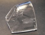
As for the nose transparency, if it's moulded in clear plastic (as with kit parts), as opposed to vac-formed, then it should sand off and polish out quite easily.
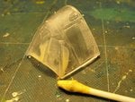
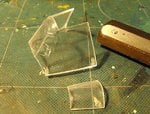
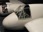
Here's a couple of before and after pics of the canopy from my 1/32nd scale Beaufighter, where I had to remove a large, very prominent horizontal frame on the side window, and a smaller frame on the 1/4 light.
This was done by 'slicing' off the bulk of the moulding using a new scalpel blade, then sanding, then very fine sanding, then polishing using 'T-Cut', with a final 'dry' polish using a soft 'yellow duster'. A coat of Future will also make it look like new when all the above has been done. As can be seen, the very distinct scratches from sanding where completely removed by the 'T-Cut', leaving a crystal-clear panel, and the photos are before applying 'Future'.
 

Attachments

  • MTO Build 002.jpg
    MTO Build 002.jpg
    41.3 KB · Views: 170
  • MTO Build 352.jpg
    MTO Build 352.jpg
    53.2 KB · Views: 183
  • MTO Build 354.jpg
    MTO Build 354.jpg
    72.4 KB · Views: 186
  • MTO Build 360.jpg
    MTO Build 360.jpg
    42.1 KB · Views: 184
loving it Gerry, dont always post as it blocks up serious comments on the build but I think its fantastic.
 
Thanks Terry. Your work on the Beaufighter canopy certainly demonstrates the pristine effect that can be achieved and reassures me about what's possible.

Thanks also pbehn and Martin and to all others who posted over the last few days for your ongoing support.

Gerry
 
Cheers Gerry for your comments! Will sure let ya know next time we're in Dublin.

Walshie's was brilliant too (thanks!) - scored 4 kits, and had to be very strong to not walk out with a few more I would like... didn't even dare going into Mark's after that! :)
Paul may be moving shop soon too, by the way. He gave me his number and e-mail to check next time we visit.

Do hope to see you too some day Terry. Working on it my friend!


--- Now back to your scheduled program :) ---
 
OK Guys, I have to admit that I have recently been distracted by a certain Footie tournament happening in Brazil. However, I haven't totally abandoned progress on the build. What I have been doing though, hasn't been particularly photogenic, concentrating on more basic building, cableing, stringing and so on. Following the magazine build sequence, I also built the second engine – but it looks just like the one I posted on page 1(!) Two of the engines, on the port wing, will just be basic builds, as they will be completely enclosed in the nacelles. The two starboard engines will be partially or wholly exposed and will need a lot of extra detailing but that won't happen until they're mounted.

Anyhow, I took a few shots of some of the more interesting bits, just to show I haven't been spending my entire life in front of the telly (although, my wife would beg to differ).

Before I abandoned the bomb aimer's position, I made a few adjustments, in line with Terry's observations. The top picture shows it as it was. The next one shows the minor adjustments, to include the securing bracket.

BombsightA11_zps091f6372.jpg

Bombaimeradjusted_zps2d60b538.jpg


What I did was to raise the triangular brackets. To allow for attachment to the bomb sight. I originally had them with the 'V' of the brackets lining up with the centre of the circle. In reality they're mounted higher and I made that adjustment, which I hope looks more realistic. If you can make it out, there's a glass reflector attached to the bubble end (front) of the sight.

The next shot should show the extended bracket from the front attached to the sight but it's very hard to see, I admit.

Bombaimeradjusted2_zpsc9e5a213.jpg


Then I set about finishing the main cabin. First I had to add all the connections to the electrical distribution panel (A). Nightmare.

Cablespider_zps62e6f0ba.jpg


What a spider's web! The build suggests that this should be done before the panel is in position but I don't know how that could be maneuvered with all those cables hanging off. BTW there is about half the amount on the left side as well. It wasn't made easier by the fact that there aren't receiving holes for the cables to slot into, Everything had to be butted and secured with superglue(!) which mostly refused to stick, except to my fingers.

Then the rest of the cabin was tackled.

cabinprofile_zps6883a37d.jpg


The cabin light was cabled and added (A). Then the hanging instrument console (B). These could only be added once the stringers were added to the roof, as they are supported from them. Then all the rest of the cables were added. They won't be as obvious from the inside, as they are obscured by some of the interior paneling. Some of the stringers were cut to allow for the final cutaways (marked in red). This side will be partially skinned which hopefully will hide a multitude!

To finish, a couple of shots showing the nose in position but not permanently attached yet, just to show how the assembly is beginning to come together.

cabinRight_zps4ceb4e53.jpg


CabinLeft_zpsb41ff859.jpg


That's it for now. Still lots of boring assembly to be tackled but I will post any real progress. I'm trying to manage my building time a little better as I have our local Nationals Show here in September and I'm hoping to have a couple of entries for that ready. That means splitting my time between the Lanc and the other builds. We'll have to see how that goes, but it may mean more time between posts.

Cheers,

Gerry
 
Great work Gerry, it's really looking the biz!

I've been meaning to ask you - have you got, or have you even seen, any references as to how the curtain, between the Navigator's station and the cockpit, was arranged? (not the sun shade curtain on the cockpit roof glazing.)
So far, I haven't found any photo clearly showing this, and the curtain was not fitted to any of the three Lancs I've been in. When I get around to building the Tamiya 1/48th scale kit, I'll have to make one (folded back) just going off a vague memory from a wartime film clip I saw many years ago. I've even closely studied the interior shots in the colour film from 'Night Bombers', to no avail.
The only other reference source I have for this is based on a verbal description from a former Lanc crew member which, although fairly helpful, does not, of course, provide the detail required for how it was mounted/attached, or precisely where, although I understand that it was on the 'arch' immediately forward of the Nav station.
 
I've been meaning to ask you - have you got, or have you even seen, any references as to how the curtain, between the Navigator's station and the cockpit, was arranged?
I'm always trying to find decent pictures too Terry but to no avail! Its one of these details that is missed from the Lanc'
like the glass armour panel which sits near the DF loop above the head buffer, only two photo's show this armour.
 
Great work Gerry, it's really looking the biz!

I've been meaning to ask you - have you got, or have you even seen, any references as to how the curtain, between the Navigator's station and the cockpit, was arranged? (not the sun shade curtain on the cockpit roof glazing.)
So far, I haven't found any photo clearly showing this, and the curtain was not fitted to any of the three Lancs I've been in. When I get around to building the Tamiya 1/48th scale kit, I'll have to make one (folded back) just going off a vague memory from a wartime film clip I saw many years ago. I've even closely studied the interior shots in the colour film from 'Night Bombers', to no avail.
The only other reference source I have for this is based on a verbal description from a former Lanc crew member which, although fairly helpful, does not, of course, provide the detail required for how it was mounted/attached, or precisely where, although I understand that it was on the 'arch' immediately forward of the Nav station.

I'm always trying to find decent pictures too Terry but to no avail! Its one of these details that is missed from the Lanc'
like the glass armour panel which sits near the DF loop above the head buffer, only two photo's show this armour.

No luck here either, even with all the books and magazines, haven't checked the 'at War' ones yet, do that after my kip...

Fingers crossed, touch wood...
 
I'm always trying to find decent pictures too Terry but to no avail! Its one of these details that is missed from the Lanc'
like the glass armour panel which sits near the DF loop above the head buffer, only two photo's show this armour.

I know what you mean Ian. I think I have a drawing of the armoured glass somewhere, and it's shown in some 'cut-away' drawings too.
From what I've been told, read, and some photos though, it wasn't always fitted (or more likely, it was removed), either as weight saving, or for easier service access to the DF loop, or both.
Same as the armoured doors in the center section. The latter are very rarely seen in operational Lancs, apart from perhaps early examples. More than one Lanc crew member has told me that they were 'dispensed with', as a potential hazard in an emergency, if they jammed, or became distorted due to enemy action, and the main spar was a big enough obstacle without having to wrestle with heavy doors. Which all lends weight to the often quoted statement that the only armour in a Lanc was the pilot's head armour.

Jan, I think there is one pic in one of the Lanc 'At War' volumes, but it's not very helpful. I'm sure I have a pic somewhere, probably in the least likely place, but where it is, I have no idea!
I'll have to dig out some old VHS cassettes with original film footage, as I definitely remember seeing it, in black and white, as the Navigator pulls back the curtain to look into the cockpit.
Could be a long, and fruitless, search ......................... and there's also the problem of how/where the curtain was mounted when H2s was fitted.......................... methinks a can opener and a worm net might be needed!!
 
Last edited:
Thanks Geo, Wurger, Gnomey, Ian, Terry and Jan for continuing to look in.

Geo, I have a set of mini drill bits but no power tool to drive them. I usually just use a pin wheel grip but, as the panel is metal, I'd still be there if I was attempting to hand drill the holes!

Terry, I looked through all my physical refs for the curtains but found nothing. I had thought I had seen something on this, more an illustration than a photo, but I can't trace it. However, I had a quick trawl through the internet and came up with these two shots which might help:

lanc_copilots_chair_zpsee6b053d.jpg


Lancaster_navigator_WWII_IWM_CH_12288_zps4a2b64de.jpg


The colour shot is from a Canadian Lanc. I can't quite decide if the yellow object is a wiring loom or a curtain/blind. If it is a wiring loom, I've not seen one of that size in that position before.
The other shot is from the IWM collection. Unfortunately it just confirms a curtain was used rather than showing any detail of how it worked. It seems to be mounted forward of the H2s equipment. I couldn't find any other shots in the sequence that might have given a clearer view.

Gerry
 
Gerry - fantastic work mate! She's not a model but a work of ART.

Terry, these any good?

STA54861.JPG


STA54862.JPG


STA54863.JPG


Pics 1,2: Squadron/Signal 5563: Lancaster Bomber Walk Around
Pic 3: Great Aircraft Of WW II: Avro Lancaster (by Mike Spick)

Btw Gerry, just booked our accommodation for the 'Airwaves' Airshow to see the 2 Lancs on Sep 7. Hope to see you there!
 

Users who are viewing this thread

Back