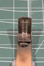
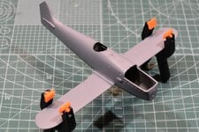
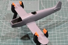
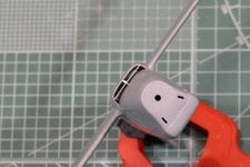
1/48 Classic Airframes Heinkel He-51

Ad: This forum contains affiliate links to products on Amazon and eBay. More information in Terms and rules

Grant Barr

Senior Airman
My next kit is the Heinkel He-51 from Classic Airframes. This is quite an old issue kit, one that I managed to pick up from ePay for a manageable price. Like all low pressure injection molded kits it will have a myriad of fit issues but if I get it right I think it will build into pretty sound representation of the real aircraft.
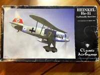
001_He-51B Box Art.jpg
As you can see from the box this kit has done a few miles, probably in multiple stashes. None-the-less the contents are pretty good and look to be complete. I've added an IP from Yahu (even though it is made for Roden or Eduard kits) that I hope to be able to fit into this one.
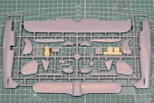
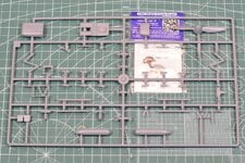
004_He-51 Sprue A Resin Clear.JPG 005_He-51 Sprue B Yahu IP.JPG
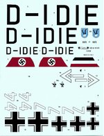
I don't have any alternate decals sourced so will be going with the kit option #3 of JG 135 at Bad Albling in early 1938. Preliminary research has not turned up too much in the way of photographic proof on this one but I will be happy to just follow what the instructions say if I still don't find out too much more about this option. The decals still look sound, but should I have any issues I'm sure I can either source from elsewhere or reproduce them (most likely option if this happens).
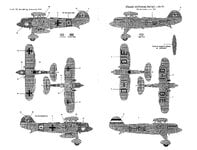
002_He-51 Colour Schemes_Page_1.jpg 003_He-51 Decals.jpg
This kit is likely to take a while to complete as I don't get a lot of time at the workbench across the warmer months of the year (for us antipodeans). Looking forward to the challenges presented by rigging and top wing alignments; fingers crossed that it won't end up in the bin if it all gets too hard... 😅
 
D-IDIE, c/n 1078 Ordered in November 1933, deliveries started April 16, 1934. The He 51 A-0s were used for trials by the "getarnnte Luftwafffe" (concealed air force), hence they wore civil markings and registrations. They also became part of the " Werbungstaffel Mitteldeutschland im DLV" (publicity squadron Central Germany of the Deutscher Luftsport-Verband or German air sports association). The DLV was a paramilitary organization training youngsters to pilots, etc. The "Reklamestaffel" was a concealment for a military squadron formed May 1, 1934 at Döberitz near Berlin. The swastika was introduced on aircraft when the concealment was ended with the official presentation of the Luftwaffe on March 1, 1935. Some 2,000 aircraft of a number of types were already in operation. A large number of these aircraft kept their civil markings, at least for some time, some were never given a military serial or code

 
Last edited:
Nice one Grant, a pretty little airplane. I've only done three rigged models and one (Swordfish) used PE. In my Norwegian Gloster Gladiator and Avia B.534 builds a while back I used knit-in elastic material and the process is explained on those threads. it was easy to use and gives a convincing result in my opinion.

Looking forward to seeing you apply your talents to this one.
 
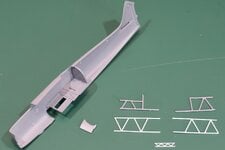
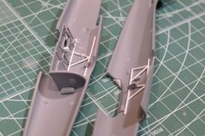
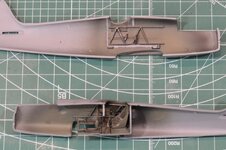
This weekend has been productive. I've made a start on the He-51 in the usual place with the cockpit. As usual I immediately found stuff that I don't think is quite right with the parts provided in the kit and set about fixing it. The first shot shows the floor and rear bulkhead already installed in the RH fuselage half. I've also included the LH & RH side internal framework as supplied with the kit (in grey) and below them are the two replacement parts I fabricated from 0.75mm rod.
006_He-51 RHS Cockpit.JPG
I did this for two reasons:
  1. When compared to a cutaway picture I found for the He-51, the thickness of the frames as supplied does not scale out properly. They are just too thick, so either sanding them down or replacing them were the 2 options I saw.
  2. Again by referring to the cutaway diagram, I could see no evidence of vertical supports within the framework at the points indicated by the kit parts. It was this issue that pushed me towards just making replacements from thinner rod.
You may also note another smaller "truss" section at the bottom. This is a cross fuselage supporting brace that sits just above the rudder pedals. The kit part is just a piece of solid bar plastic, whereas the drawing I have indicates it is really a type of small "Warren" truss. I was in the mood to make some more trusses now I'd started so this one got churned out as well. It ended up being a bit too big (height-wise) but as it will be almost impossible to see I will use it anyway (I was having way too much fun making stuff from scratch...).

I've also dropped the LHS cockpit access door into the shot. As I noted in the intro this kit will have plenty of fit issues to resolve and this is one. The rear top part of the door was quite badly deformed so I trimmed it back and added a small piece of flat styrene that can be shaped to make the door fit properly.

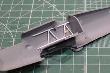
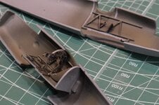
In this next shot I've just mocked up the RHS internal framework to ensure everything will fit properly once installed. You can see I've already fitted the throttle and other lever (no idea on the function of this one - trim perhaps?). My biggest concern here was to make sure the framework would not interfere with the IP and the cross brace I've made.
007_He-51 RHS Cockpit Frame Mock.JPG
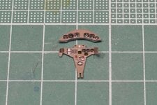
Speaking of the IP - I am quite impressed with the Yahu item. I've not used Yahu before but the level of detail on this part is superb, at least as good as any of the other manufacturers out there.
008_He-51 Yahu IP Cleaned Up.JPG
That is about as far as I got tonight. I wanted to get the main pieces of the cockpit all assembled tonight but found that I still need to do a lot more test fitting and adjustment to make sure everything fits as planned. Better to go a bit slower now and get it right, rather than bollock's it all up and have to redo it.

I've only done three rigged models and one (Swordfish) used PE.
Andy - your comment got me to thinking. The last biplane I built must be over 40 years ago now and I spent half the afternoon rattling around in the back of my head trying to remember what it was. Then it hit me - a 1/72 Matchbox Fairey Seafox (image courtesy of matchboxkits.org), slapped together with too much glue, painted with Humbrol enamels brushed on, poorly applied decals and no rigging. I used to love those multi-coloured kits!!! Those were the days!
PK-036-5-01.jpg
 
Thanks again to all those looking in on my ramblings...

I did make some progress this weekend despite being a bit time poor.

First up, I managed to get the scratch-built framework in place on both sides of the fuselage. I had to make a couple of small adjustments to the height and make a few other tweaks to get it to fit without interfering with other cockpit components. Its probably not quite correct, especially on the port side but I'm happy enough to leave it as is. Once the framework was in place I could then fit all the other various levers and knobs in the appropriate locations and give the whole thing a quick undercoat.
009_He-51 Cockpit Fitted.JPG 010_He-51 Cockpit Undercoated.JPG
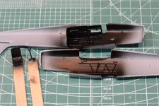
Once the undercoat dried enough I set to work on getting the RLM02 laid down and try to do a little shading and lightening of the frame and seat. It kind of worked, I was probably a little too timid in the application of darker/lighter shades as I've not tried this before and I didn't want to stuff it up so badly that I would have to start again.
011_He-51 Cockpit Painted.JPG 012_He-51 Seat & Belts Painted.JPG
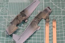
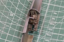
I also tried to weather the cockpit a bit with some chipping and generally "dirtying up" via a dark oily wash. Again its reasonably subtle, but hopefully you can see the effects. Once all the various bits were painted and weathered/chipped I managed to get the two halves ready for joining. As you can see the cockpit looks detailed without being so busy that you lose the overall effect (at least I think that's what I achieved :dontknow:)
013_He-51 Cockpit Fitted & Painted.JPG 014_He-51 Cockpit Fitted & Painted 2.JPG 015_He-51 Cockpit Fitted & Weathered.JPG
Since taking these photos, I have closed up the fuselage but have not managed to take any shots of the progress. The two halves did have a bit of a twist - making the process a bit challenging and the somewhat hit-and-miss moulding will make the clean up process a bit more of a challenge than I hoped. This will be a job for the next week or so.

I also took the chance to check on the fit of the lower wing to the fuselage. Oh boy! Is that one going to be a doozy. There are gaps in the wing root join of nearly 1mm on both sides. A quick look for the causes reveal that the lower wing is bowed downwards, giving it some unwanted anhedral. I will probably need to drop the wing into some hot water and try to take the bow out of the wing - never tried this before so fingers crossed I will get it to work. Once straightened I suspect the gap in the wing roots will still be there but hopefully it will be less than 0.5mm, which is a much better gap to fix with plastic card.
 
I have progress to report! Over the past 3 weeks I have been trying to grab a few minutes here and there to work on this kit.

In the first post of this thread I mentioned that I anticipated this kit would require a fair bit of fiddly test fitting and adjustment to make everything look right. I can confirm that this was indeed the case. Having buttoned up the fuselage I did a test fit of the lower wing to find that:
  1. The lower wing was bowed downwards at the tips, giving some anhedral, and
  2. The wing root had some substantial gaps that would require some filler.
The next couple of photos confirm the gaps did need some plastic card to get it right. I was reasonably lucky in that the downward bow of the wing was able to be corrected without too much drama, and this contributed in a small way to reducing the gaps to the fuselage.
016_He-51 Lower Wing Fitted & Shimmed RHS.JPG 017_He-51 Lower Wing Fitted & Shimmed LHS.JPG
If you look closely at the fuselage seams you can see that it was a little bit of an issue to get it lined up as well - a fair bit of twisting and pulling was required to get it to be anywhere near straight. It's not 100% perfect but I can live with that.

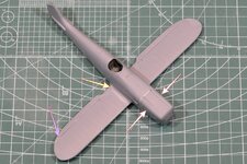
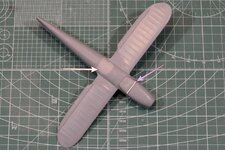
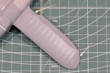
These next shots are the issues that I found with the lower wing insert, the engine top cowl and the radiator. Firstly the engine cowl was a right palaver. It was both too short and too wide to fit properly onto the fuselage. The white arrows indicate where I had to pare down the width of the panel and you can see the white styrene card shim inserted at the end of this panel. I've also highlighted with the yellowish arrow where I had to do quite a bit of filler work in both wing roots to get them to look anywhere near accurate. I probably should note at this point that I think the wings are too thick in profile - but given the age of the kit and the fact it's from a short production run I am not bothering to try to correct this.
018_He-51 Lower Wing & Engine Cowl Fit Issues.JPG 019_He-51 Lower Wing & Radiator.JPG
The shot of the underside shows where a great deal of filler was required to fix where the fuselage panel moulded with the lower wings was just completely wrong. Looking at this aircraft in profile shows a pronounced bulge/curvature to the fuselage under the wing. The part I have resulted in no bulge and the panel had a pronounced lip where it jumped back out to the fuselage halves a the rear joint. I thought about using styrene cards layered to fix this issue but ended up just using Tamiya filler finished with Mr Surfacer 1000 to get the desired profile shape. I think this would have been marginally quicker than using plastic card and then shaving that down to shape. This shot also shows the radiator housing panel. Unfortunately I neglected to take any shots of this housing, but I took to it with the Dremel and shaved it down in thickness so it looked much more to scale. This also meant that the radiator blanking panel as supplied was the wrong shape/size, but I intended to replace this with thinner card anyway. You can just see the revised panel poking out the front of the housing.

These two head on shots show both the revised radiator housing and blanking panel and the additional holes made in the upper nose panel. All the reference photos I have show clearly the two vertical slots (I think mine are fractionally too far out to the sides). Less clear are what appear to be a series of four small slots along the joint with the upper cowl. At least I am hoping they are holes, my other thought was that they could just be shadows from something like hinges at the front of the cowl (I considered this to be less likely).
020_He-51 Radiator Blanking Panel.JPG 021_He-51 Nose Upper Panel Vents.JPG
Finally, I have also done quite a bit of work on thinning the trailing edges of the lower wing and horizontal stabilisers, along with reshaping the leading edges to remove some nasty mold lines and general messiness. For the lower wing shot if you look closely you should be able to see where I have filed and sanded back into the wing ridges to help thin down the trailing edges - they were over 1mm thick and looked really shoddy.
022_He-51 Lower Wing Trailing Edges.JPG 023_He-51 Small Parts Clean Up.JPG
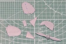
The last shot shows a whole bunch of smaller parts that I have separated from the sprues and spent some time cleaning up and re-scribing in preparation for fitting the fuselage. It's been a bit tedious and the quality of some parts is pretty bad but I still think I can get this model to look pretty smart by the time I've cleaned everything up. It certainly has been a bigger challenge than the latest kits available from the big manufacturers!

With luck I will get a bit more time at the workbench tonight. Another big weekend of triathlon training is coming up but I do hope to have a few minutes of down time here and there to keep the progress going. As always, thanks for looking in on my latest project, cheers!
 
Yes there were the hinges ... however judging by all pictures of the He-15 with the hinges seen it looks like there were two variants of them. The first one had the outside hinges riveted while the second one inside. IMHO the second one gave more smooth front of the engine cowling because there were protruding their pivot joints only.

the first variant
Heinkel-He-51B-nose-1.jpg

He-51_hinges_2.jpg

Heinkel_He_51.jpg

the source: the net and Heinkel He 51B nose profile view showing wheel damage after a heavy landing ebay 01

the second variant ... the same noticed in the pic posted above by Andy
Bild 102-04674b.jpg

Heinkel_He_51_.jpg

he51.jpg


he51 hinges.jpg

the source: the net
 

Users who are viewing this thread

Back