- Thread starter
- #441
ccheese
Member In Perpetuity
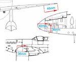
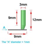
I've got to thank Wojtek for this. He sent me diagrams of the pitot tube measurements (in 1/24 scale) and also sent me measurements for the placement under the port wing. Hope to get it painted tomorrow.
Charles
Charles
Attachments
Last edited:

 And the help that was lent was above and beyond as is always the case here. If I may, the exhaust stack stagger may be due to the the fact that they may have used the same head casting on both sides of the engine. Meaning that if on the left side if you start with a intake port at the front of the head it ends at the rear with a exhaust port at the rear. [ xo xo xo xo xo xo ] Now, if the same head is used on the right side you start with a exhaust valve at the front and end with a intake at the rear. [ox ox ox ox ox ox ] And if the heads are aligned evenly with one another on the block you get the stagger. They do this in the automotive world on a regular basis. Hope this clears it up some. I am not sure if they did it this way. Someone with more knowledge than I will have to confirm it. And again, SUPERB WORK SIR!