- Thread starter
- #101
Crimea_River
Marshal
Thanks Evan. The coolant tank is the one in front of the engine bearer. I'm talking about the one that's within the bearer. This one only appears on the port side. See here with arrows:

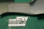
Anyhoo, I progressed the cockpit sidewalls today after having decided to use the parts from my Hasegawa G-6 which are surplus since I got a resin upgrade for that kit. To get these parts to fit, I had to make a few mods as described below. I thought that I had taken pictures earlier in my build that showed the existing ICM cockpit wall details and so I launched into thinning the walls before taking a picture. Unfortunately, I was mistaken so I can't show you what the wall looked like before I hacked away at it.
The first pic shows one of the Hasegawa parts next to the thinned fuselage wall. I carefully preserved the lip at the top of the cockpit wall as this forms the seat for the canopy. The dry-fitted cockpit/engine assembly was used to mark the walls where the Hasegawa piece would go. Note that I had to extend the wall piece with some built-up card to pick up what would have otherwise become a gap between the ICM floor and the Hasegawa wall. Odd that there would be so much of a difference but, oh well.
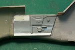
The second pic has the starboard wall glued in place with the lower extension cut to the right length and a filler piece added to close the gap where the instrument panel will go. Next step will be removal of some of the details that will be replaced by the PE bits and sanding the parts to blend in the extensions.
Thanks for continuing to follow this build.
Anyhoo, I progressed the cockpit sidewalls today after having decided to use the parts from my Hasegawa G-6 which are surplus since I got a resin upgrade for that kit. To get these parts to fit, I had to make a few mods as described below. I thought that I had taken pictures earlier in my build that showed the existing ICM cockpit wall details and so I launched into thinning the walls before taking a picture. Unfortunately, I was mistaken so I can't show you what the wall looked like before I hacked away at it.
The first pic shows one of the Hasegawa parts next to the thinned fuselage wall. I carefully preserved the lip at the top of the cockpit wall as this forms the seat for the canopy. The dry-fitted cockpit/engine assembly was used to mark the walls where the Hasegawa piece would go. Note that I had to extend the wall piece with some built-up card to pick up what would have otherwise become a gap between the ICM floor and the Hasegawa wall. Odd that there would be so much of a difference but, oh well.
The second pic has the starboard wall glued in place with the lower extension cut to the right length and a filler piece added to close the gap where the instrument panel will go. Next step will be removal of some of the details that will be replaced by the PE bits and sanding the parts to blend in the extensions.
Thanks for continuing to follow this build.
Attachments
Last edited:

")