Great work so far Wayne!
Navigation
Install the app
How to install the app on iOS
Follow along with the video below to see how to install our site as a web app on your home screen.
Note: This feature may not be available in some browsers.
More options
You are using an out of date browser. It may not display this or other websites correctly.
You should upgrade or use an alternative browser.
You should upgrade or use an alternative browser.
**** DONE: 1/48 Westland Whirlwind Mk.I - Allied Manufactured Aircraft
Ad: This forum contains affiliate links to products on Amazon and eBay. More information in Terms and rules
More options
Who Replied?- Thread starter
- #82
Thanks Guys....some more to see.
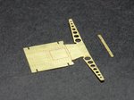
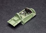
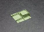
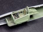
The rear canopy decking has been 'folded' painted and fitted...with a dry fit of the entire assembly to the starboard fuselage....oh and the little straight piece in the first pic was replaced with plasticard...when I was placing it...PING....and that was the end of that....new piece required!
The rear canopy decking has been 'folded' painted and fitted...with a dry fit of the entire assembly to the starboard fuselage....oh and the little straight piece in the first pic was replaced with plasticard...when I was placing it...PING....and that was the end of that....new piece required!
Attachments
Last edited:
Airframes
Benevolens Magister
Looks the biz !
Any idea what those 'boxes' are, behind the seat ?
Any idea what those 'boxes' are, behind the seat ?
Crimea_River
Marshal
The dreaded PING but you covered it well.
It's refreshing to hear you make mistakes like the rest of us mortals. 
Catch22
Major
Nice.
Aaron Brooks Wolters
Brigadier General
Very nice Wayne. One day I hope to be able to put the effort into these that you do.
Looks great so far Wayne!
Donivanp
Lieutenant Colonel
That is a beautiful cockpit and interment panel, great work with the PE.
- Thread starter
- #91
thanks very much fellas.....
Terry, no idea what it is...thought you might know.....the only word that has come up in my trying to answer is Accumulator...
Andy...guess what I found yesterday...10 feet away in the family room...must have landed on me then fell off me later....can't use it now!
Terry, no idea what it is...thought you might know.....the only word that has come up in my trying to answer is Accumulator...
Andy...guess what I found yesterday...10 feet away in the family room...must have landed on me then fell off me later....can't use it now!
All I got is this, but it shows no box ?

And this guy at large scale planes has what look like 2 black radios ?
1/32 scratchbuilt Westland Whirlwind - Page 20 - Works in Progress - LSP Forums - Page 20
1/32 scratchbuilt Westland Whirlwind - Page 20 - Works in Progress - LSP Forums - Page 20
- Thread starter
- #94
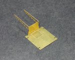
I got that pic too karl, it does show 4 securing bolts for a box?
Yes I think your right, seems a logical place for a radio or batteries etc
Airframes
Benevolens Magister
Yes, my first thoughts were radio transmitter and receiver, or 'TR9' type radio (or the VHF replacement -can't remember the number) and battery, both of which were semi-matt black.
Apparently it had 2 x type D accumulator in that space, pic on bottom of this link.
The Unofficial Airfix Modellers' Forum ? View topic - John's Westland Whirlwind
The Unofficial Airfix Modellers' Forum ? View topic - John's Westland Whirlwind
Apparently it had 2 x type D accumulator in that space,
Accumulator is just 'old speak' for a battery.
Cheers
Steve
Yup I thought as much, sounds very Heath Robison saying accumulator !
Last edited:
Found this explanation
As originally conceived the TR9D radio was intended to occupy the space on the "parcel shelf" under the canopy – so the modellers are not entirely wrong. The Whirlwind seat back was simply two dural poles with a leather cover stretched over them. It was intended that this cover could be removed to gain access to the accumulators, oxygen bottles and other kit behind the seat. When the requirement to accommodate the TR1133 VHF set was introduced (Mod 8) together with the need for armour behind the seat (Mod 33) - which prevented access to the components behind the seat - the rear fuselage was substantially redesigned to incorporate a hatch on the starboard side – where previously there was none. With the further requirement to install R3003 IFF and the tropical ration tray the hatch was enlarged. As a part of this rearrangement the accumulators were moved up onto the "parcel shelf" and the radio relocated to behind the pilot's seat with the oxygen bottles, Plessey revolver signal pistol, R3003 etc.
I've never seen a photo of this part of the aircraft with the accumulators installed, but I seem to recall the wiring diagram for the aircraft shows them installed one behind the other with the longer sides running port-starboard i.e. as per your model picture but with each accumulator rotated 90 degrees. There were always 2 accumulators (The Whirlwind had 24 volt electrics – maybe the 1st RAF aircraft to do so????) but the type changed during the aircraft's life from 2 Type "B" accumulators to 2 Type "D" ones from P7106 onwards (and presumably retro-fitted to earlier aircraft). These accumulators are standard issue components so there should be photo in one of the generic electrical APs.
Note also that on very early aircraft the remote contactor for the TR9D was also installed on the accumulator tray, but was soon relocated when it was realised that it would be more useful if placed somewhere where the pilot could actually reach it.
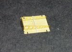
Better pic of the type D accumulator

As originally conceived the TR9D radio was intended to occupy the space on the "parcel shelf" under the canopy – so the modellers are not entirely wrong. The Whirlwind seat back was simply two dural poles with a leather cover stretched over them. It was intended that this cover could be removed to gain access to the accumulators, oxygen bottles and other kit behind the seat. When the requirement to accommodate the TR1133 VHF set was introduced (Mod 8) together with the need for armour behind the seat (Mod 33) - which prevented access to the components behind the seat - the rear fuselage was substantially redesigned to incorporate a hatch on the starboard side – where previously there was none. With the further requirement to install R3003 IFF and the tropical ration tray the hatch was enlarged. As a part of this rearrangement the accumulators were moved up onto the "parcel shelf" and the radio relocated to behind the pilot's seat with the oxygen bottles, Plessey revolver signal pistol, R3003 etc.
I've never seen a photo of this part of the aircraft with the accumulators installed, but I seem to recall the wiring diagram for the aircraft shows them installed one behind the other with the longer sides running port-starboard i.e. as per your model picture but with each accumulator rotated 90 degrees. There were always 2 accumulators (The Whirlwind had 24 volt electrics – maybe the 1st RAF aircraft to do so????) but the type changed during the aircraft's life from 2 Type "B" accumulators to 2 Type "D" ones from P7106 onwards (and presumably retro-fitted to earlier aircraft). These accumulators are standard issue components so there should be photo in one of the generic electrical APs.
Note also that on very early aircraft the remote contactor for the TR9D was also installed on the accumulator tray, but was soon relocated when it was realised that it would be more useful if placed somewhere where the pilot could actually reach it.
Better pic of the type D accumulator
Last edited:
Users who are viewing this thread
Total: 1 (members: 0, guests: 1)