German fighters and training aircrafts

Ad: This forum contains affiliate links to products on Amazon and eBay. More information in Terms and rules

In autumn 1937, the German Ministry of Aviation asked various designers for a new fighter to fight alongside the Messerschmitt Bf 109, Germany's front line fighter. Although the Bf 109 was an extremely competitive fighter, the Ministry of Aviation was worried that future foreign designs might outclass it, and wanted to have new aircraft under development to meet these possible challenges. Kurt Tank responded with a number of designs, most incorporating liquid-cooled inline engines. However, it was not until a design was presented using the air-cooled, 14-cylinder BMW 139 radial engine that the Ministry of Aviation's interest was aroused. As this design used a radial engine, it would not compete with the inline-powered Bf 109 for engines, when there were already too few DB 601's to go around. This was not the case for competing advanced designs like the Heinkel He 100 or Focke-Wulf Fw 187, where production would compete with the 109 or Messerschmitt Bf 110 for engine supplies. After the war, Tank denied a rumour that he had to "fight a battle" with the Ministry to convince them of the radial engine's merits.

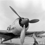
At the time, the use of radial engines in land-based fighters was relatively rare in Europe, as it was believed that their large frontal area would cause too much drag on something as small as a fighter. Tank was not convinced of this, having witnessed the successful use of radial engines by the US Navy, and felt a properly streamlined installation would eliminate this problem. The hottest point on any air-cooled engine are the cylinder heads, located along the outside diameter of a radial engine. In order to provide sufficient air to cool the engine, the cowling needed to allow airflow at this outer edge, which generally resulted in the majority of the front face of the engine being left open to the air. During the late 1920s, NACA led development of a dramatic improvement by placing an airfoil-shaped ring around the outside of the cylinder heads. The shaping accelerated the air as it entered the front of the cowl, increasing the total airflow, and allowing the opening in front of the engine to be made smaller. Tank introduced a further refinement to this basic concept. He suggested placing most of the airflow components on the propeller itself, in the form of a oversized propeller spinner whose outside diameter was the same as the engine itself. The cowl around the engine proper was greatly simplified, essentially a basic cylinder. Air entered through a small hole at the center of the propeller, and was directed through ductwork in the spinner so it was blowing rearward along the cylinder heads. To provide enough airflow, a cone was placed in the center of the hole, over the propeller hub, which was intended to compress the airflow and allow a smaller hole to be used. In theory, the tight-fitting cowling also provided some thrust due to the compression and heating of air as it flowed through the cowling.

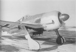
As to the rest of the design philosophy, Tank wanted something more than an aircraft built only for speed. Tank outlined the reasoning: The Messerschmitt 109 [sic] and the British Spitfire, the two fastest fighters in world at the time we began work on the Fw 190, could both be summed up as a very large engine on the front of the smallest possible airframe; in each case armament had been added almost as an afterthought. These designs, both of which admittedly proved successful, could be likened to racehorses: given the right amount of pampering and easy course, they could outrun anything. But the moment the going became tough they were liable to falter. During World War I, I served in the cavalry and in the infantry. I had seen the harsh conditions under which military equipment had to work in wartime. I felt sure that a quite different breed of fighter would also have a place in any future conflict: one that could operate from ill-prepared front-line airfields; one that could be flown and maintained by men who had received only short training; and one that could absorb a reasonable amount of battle damage and still get back. This was the background thinking behind the Focke-Wulf 190; it was not to be a racehorse but a Dienstpferd, a cavalry horse. A main feature of the Fw 190 was its wide landing gear. Tank appreciated that operating from primitive airfields in wartime would require a stable undercarriage — a lesson learned from witnessing the difficulty of moving machinery in the First World War. The wide-track landing gear spacing gave it better ground handling characteristics, and it suffered fewer ground accidents than the Bf 109 with its narrow-track landing gear. The undercarriage was designed to withstand a sink rate of 15 feet per second (4.5 meters per second, 900 feet per minute), double the strength factor usually required. Hydraulic wheel brakes were used.

Most aircraft of the era used cables and pulleys and pulleys to operate their controls. The cables tended to stretch, resulting in 'give' and 'play' that made the controls less crisp and responsive, and requiring constant maintenance to correct. For the new design, the team replaced these with rigid pushrods to eliminate this problem. Another innovation was making the controls as light as possible. The maximum resistance of the ailerons was limited to eight pounds, as the average man's wrist could not exert a greater force. The empennage (tail assembly) featured relatively small horizontal and vertical surfaces. The design team also attempted to minimize changes in the aircraft's trim at varying speeds, thus reducing the pilot's workload. They were so successful in this regard that they found in-flight-adjustable aileron and rudder trim tabs were not necessary. Small, fixed tabs were fitted to control surfaces and adjusted for proper balance during initial test flights. Only the elevator trim needed to be adjusted in flight (a feature common to all aircraft). This was accomplished by tilting the entire horizontal tailplane, which could be adjusted by an electric motor from a -3 to a +5 angle of incidence. Another aspect of the new design was the extensive use of electrically powered equipment instead of the hydraulic systems used by most aircraft manufacturers of the time. On the first two prototypes, the main landing gear was hydraulic. Starting with the third prototype, the undercarriage was operated by push buttons controlling electric motors in the wings, and was kept in position by electric up and down-locks.[12] The armament was also loaded and fired electrically. Tank believed that service use would prove that electrically powered systems were more reliable and more rugged than hydraulics, electric lines being much less prone to damage from enemy fire.

As was the case for the 109, the 190 featured a fairly small wing planform with relatively high wing loading. This presents a trade-off in performance; an aircraft with a smaller wing suffers less drag in most flight and therefore flies faster and may have better range. However, it also means the wing cannot generate extra lift as easily, which is needed for maneuvering or flight at high altitudes.The wings spanned 9.5 m (31 ft 2 in) and had an area of 15 m² (161 ft²). The wing was designed using the NACA 23015.3 airfoil at the root and the NACA 23009 airfoil at the tip.
 

Attachments

  • Focke Wulf Fw-190 001.jpg
    Focke Wulf Fw-190 001.jpg
    138.3 KB · Views: 219
  • Focke Wulf Fw-190 002.jpg
    Focke Wulf Fw-190 002.jpg
    50.2 KB · Views: 241
  • Focke Wulf Fw-190 003.jpg
    Focke Wulf Fw-190 003.jpg
    94.7 KB · Views: 220
  • Focke Wulf Fw-190 004.jpg
    Focke Wulf Fw-190 004.jpg
    81.6 KB · Views: 219
  • Focke Wulf Fw-190 005.jpg
    Focke Wulf Fw-190 005.jpg
    72.5 KB · Views: 227
  • Focke Wulf Fw-190 006.jpg
    Focke Wulf Fw-190 006.jpg
    120.3 KB · Views: 224
  • Focke Wulf Fw-190 007.jpg
    Focke Wulf Fw-190 007.jpg
    67.8 KB · Views: 224
  • Focke Wulf Fw-190 008.jpg
    Focke Wulf Fw-190 008.jpg
    74.1 KB · Views: 230
The first prototype, the Fw 190 V1 (civil registration D-OPZE), powered by a 1,550 PS (1,529 hp, 1,140 kW) BMW 139 14-cylinder two-row radial engine, first flew on 1 June 1939. It soon showed exceptional qualities for such a comparatively small aircraft, with excellent handling, good visibility and speed (initially around 610 km/h (380 mph)).[14] The roll rate was 162° per second at 410 km/h (255 mph), but the aircraft had a high stall speed of 205 km/h (127 mph). The cockpit, located directly behind the engine, quickly became uncomfortably hot. During the first flight, the temperature reached 55 °C (131 °F), after which Focke Wulf's chief test pilot, Hans Sander commented, "It was like sitting with both feet in the fireplace." Flight tests soon showed that the expected benefits of Tank's cooling design did not materialize, so after the first few flights, this arrangement was replaced by a smaller, more conventional spinner that covered only the hub of the three-blade VDM propeller. In an attempt to increase airflow over the tightly cowled engine, a 10-blade fan was fitted at the front opening of the redesigned cowling and was geared to be driven at 3.12 times faster than the propeller shaft's speed. This quickly became standard on the 190 and nearly all other German aircraft powered by the BMW 801. In this form the V1 first flew on 1 December 1939, having been repainted with the Luftwaffe's Balkenkreuz and with the Stammkennzeichen (factory code).[17] RM+CA. The Fw 190 V2, designated with the Stammkennzeichen alphabetic ID code of FL+OZ (later RM+CB) first flew on 31 October 1939 and was equipped from the outset with the new spinner and cooling fan. It was armed with one Rheinmetall-Borsig 7.92 mm (.312 in) MG 17 machine gun and one 13 mm (.51 in) MG 131 machine gun in each wing root.

Even before the first flight of the Fw 190 V1, BMW was bench testing a larger, more powerful 14-cylinder two-row radial engine, the BMW 801. This engine introduced a pioneering example of an engine management system called the Kommandogerät (command-device): in effect, an electro-mechanical computer which set mixture, propeller pitch (for the constant speed propeller), boost, and magneto timing. This reduced the pilot's work load to moving the throttle control only, with the rest of the associated inputs handled by the Kommandogerät. The drawback was slight and minor surges that made the Fw 190 harder to fly in close formations. Tank asserted the device did not work well. One of the faults in the system was the violent switching in of the high gear of the supercharger as the aircraft climbed. During a test flight, Tank carried out a loop at medium altitude. Just as he was nearing the top of the loop, at 2,650 m (8,700 ft), the supercharger's high gear kicked in with a jerk. The Fw 190 was on its back, with little airspeed. The sudden change in torque hurled the aircraft into a spin. Tank's artificial horizon toppled (the cause is not explained). Although Tank did not know whether he was in an upright or inverted spin, he managed to recover after a loss of altitude. The rough transition was smoothed out and the supercharger's gear-change could engage without incident.

The Ministry of Aviation convinced Focke-Wulf and BMW to abandon the 139 engine in favour of the new engine. The BMW 801 engine was similar in diameter to the 139, although it was heavier and longer by a considerable margin. This required Tank to redesign the Fw 190, resulted in the abandonment of the V3 and V4. The V5 became the first prototype with the new engine, being fitted with the 1,560 PS (1,539 hp, 1,147 kW) BMW 801C-0. Much of the airframe was strengthened and the cockpit was moved back in the fuselage, which reduced the troubles with high temperatures and for the first time provided space for nose armament. It also reduced visibility in nose-high attitudes, notably when taxiing on the ground. A 12-blade cooling fan replaced the earlier 10-blade unit, and was likewise installed in front of the engine's reduction gear housing, still running with the original 3.12:1 reduction ratio, which was standardised for BMW-powered Fw 190s. The propeller shaft passed through the fan's central plate, which was made of cast magnesium. The fan provided cooling air not only for the engine cylinders' fins, but also for the annular oil cooler, which was located in the forward part of the cowling. The oil cooler was protected by an armoured ring which made up the front face of the cowling. A small hole in the centre of the spinner also directed airflow to ancillary components. Even with the new engine and the cooling fan, the 801 suffered from high rear-row cylinder head temperatures, which in at least one case resulted in the detonation of the fuselage-mounted MG 17 ammunition.

The vertical tail shape was also changed and the rudder tab was replaced by a metal trim strip adjustable only on the ground. New, stiffer undercarriage struts were introduced, along with larger diameter wheels. The retraction mechanism was changed from hydraulic to electrically powered, which became a hallmark of later Focke-Wulf aircraft system designs, and new fairings of a simplified design were fitted to the legs. Another minor change was that the rearmost sections of the sliding canopy were redesigned by replacing the plexiglas glazing with duralumin panels. As this section was behind the pilot's seat, there was little visibility lost. At first, the V5 used the same wings as the first two prototypes, but to allow for the larger tyres, the wheelwells were enlarged by moving forward part of the leading edge of the wing root; the wing area became 15.0 m² (161 ft²). The V5 first flew in the early spring of 1940. The weight increase with all of the modifications was substantial, about 635 kg (1,400 lb), leading to higher wing loading and a deterioration in handling. Plans were made to create a new wing with more area to address these issues. In its original form, this prototype was called the V5k for kleine Fläche (small surface). In August 1940 a collision with a ground vehicle damaged the V5 and it was sent back to the factory for major repairs. This was an opportune time to rebuild it with a new wing which was less tapered in plan than the original design, extending the leading and trailing edges outward to increase the area. The new wing had an area of 18.30 m² (197 ft²), and now spanned 10.506 m (34 ft 5 in). After conversion, the aircraft was called the V5g for große Fläche (large surface). Although it was 10 km/h (6 mph) slower than when fitted with the small wing, V5g was much more manoeuvrable and had a faster climb rate. This new wing platform was to be used for all major production versions of the Fw 190.

Fw 190 A-0 were the pre-production series ordered in November 1940, with a total of 28 were built. Because they were built before the new wing design was fully tested and approved, the first nine A-0s had small wings. All were armed with two synchronised 7.92 mm (.312 in) MG 17 machine guns mounted in the forward fuselage, one MG 17 in each wing root, and one MG 17 in each of the outboard wings. They were different from later A-series Fw 190s: they had shorter spinners, the armoured cowling ring was a different shape, with a scalloped hinge on the upper, forward edge of the upper engine cowling, and the bulges covering the interior air intakes on the engine cowlings were symmetrical "teardrops". Also, the panels aft of the exhaust pipes had no cooling slots. Several of these aircraft were later modified for testing engines and special equipment. The first unit to be equipped with the A-0 was Erprobungsstaffel 190, formed in March 1941 to help iron out any technical problems and approve the new fighter before it would be accepted for full operational service in mainstream Luftwaffe Jagdgeschwader. At first, this unit, commanded by Oblt. Otto Behrens, was based at the Luftwaffe's central Erprobungsstelle facility at Rechlin, but it was soon moved to Le Bourget. Engine problems plagued the 190 for much of its early development, and the entire project was threatened several times with a complete shutdown. Had it not been for the input of Behrens and Karl Borris, both of whom had originally enlisted in the Luftwaffe as mechanics, the Fw 190 program might have died before reaching the front lines. Both men indicated that the Fw 190's outstanding qualities outweighed its deficiencies during several Ministry of Aviation commissions that wished to terminate the program. Some 50 modifications were required before the Ministry of Aviation approved the Fw 190 for deployment to Luftwaffe units.
 

Attachments

  • Focke Wulf Fw-190 009.jpg
    Focke Wulf Fw-190 009.jpg
    67.3 KB · Views: 213
  • Focke Wulf Fw-190 0010.jpg
    Focke Wulf Fw-190 0010.jpg
    140.7 KB · Views: 220
  • Focke Wulf Fw-190 0011.jpg
    Focke Wulf Fw-190 0011.jpg
    115.8 KB · Views: 217
  • Focke Wulf Fw-190 0012.jpg
    Focke Wulf Fw-190 0012.jpg
    126.3 KB · Views: 217
  • Focke Wulf Fw-190 0013.jpg
    Focke Wulf Fw-190 0013.jpg
    115.1 KB · Views: 221
  • Focke Wulf Fw-190 0014.jpg
    Focke Wulf Fw-190 0014.jpg
    116.4 KB · Views: 227
  • Focke Wulf Fw-190 0015.jpg
    Focke Wulf Fw-190 0015.jpg
    110.1 KB · Views: 218
  • Focke Wulf Fw-190 0016.jpg
    Focke Wulf Fw-190 0016.jpg
    123.1 KB · Views: 212
The Focke-Wulf Fw 190 Würger was used by the Luftwaffe during the Second World War in a variety of roles. Like the Messerschmitt Bf 109, the Fw 190 was employed as a "workhorse", and proved suitable for a wide variety of roles, including air superiority fighter, strike fighter, ground-attack aircraft, escort fighter, and operated with less success as a night fighter. It served on all the German fronts; Eastern Front, Western Front, North African Campaign and the Defence of the Reich. When it was first introduced in August 1941 it was quickly proven to be superior in all but turn radius to the Royal Air Force (RAF) front-line fighter, the Spitfire Mk. V variant. The 190 wrested air superiority away from the RAF until the introduction of the vastly improved Spitfire Mk. IX in July 1942 restored qualitative parity. The Fw 190 made its air combat debut on the Eastern Front much later, in November/December 1942. The Fw 190 made a significant impact seeing service as a fighter and fighter-bomber. The fighter and its pilots proved just as capable as the Bf 109 in aerial combat, and in the opinion of German pilots that flew both German fighters, the Fw 190 presented increased firepower and manoeuvrability at low to medium altitude.

The Fw 190 became the backbone of Jagdwaffe (Fighter Force) along with the Bf 109. On the Eastern Front, owing to its versatility, the Fw 190 was used in Schlachtgeschwader (Attack Wings) which were specialised ground attack units. The units achieved much success against Soviet ground forces. As an interceptor, the Fw 190 underwent improvements to make it effective at high altitude allowing the 190 to maintain relative parity with its Allied counterparts. The Fw 190A series' performance decreased at high altitudes (usually 6,000 m (20,000 ft) and above) which reduced its usefulness as a high-altitude fighter, but these complications were mostly rectified in later models, notably the Focke-Wulf Fw 190D variant which was introduced in September 1944. In spite of its successes, it never entirely replaced the Bf 109. The Fw 190 was well liked by its pilots. Some of the Luftwaffe's most successful fighter aces flew the Fw 190, including Otto Kittel with 267 victories, Walter Nowotny with 258 victories and Erich Rudorffer with 222 claimed kills. A great many of their kills were claimed while flying the Fw 190.
 

Attachments

  • Focke Wulf Fw-190 0017.jpg
    Focke Wulf Fw-190 0017.jpg
    124 KB · Views: 212
  • Focke Wulf Fw-190 0018.jpg
    Focke Wulf Fw-190 0018.jpg
    105.1 KB · Views: 219
  • Focke Wulf Fw-190 0019.jpg
    Focke Wulf Fw-190 0019.jpg
    84.8 KB · Views: 214
  • Focke Wulf Fw-190 0020.jpg
    Focke Wulf Fw-190 0020.jpg
    81.6 KB · Views: 215
  • Focke Wulf Fw-190 0021.jpg
    Focke Wulf Fw-190 0021.jpg
    159.1 KB · Views: 215
The Bücker Bü 133 Jungmeister was a very successful single seat aerobatic trainer used as an advanced trainer by the Luftwaffe and as an aerobatic display aircraft after the war. Bücker's first design, the Bü 131 Jungmann, was a successful two-seat biplane basic trainer. This was a very standard biplane, with a steel tube fuselage, wooden wings and a fabric covering, and was adopted by the Luftwaffe as its standard basic trainer. The success of this aircraft allowed Bücker to move from its original factory at Johannisthal to a new plant at Rangsdorf, and the extra manufacturing capability at the new factory allowed the company to develop a new aircraft.

The Bü 133 Jungmeister was essentially a smaller, lighter, single-seat version of the Bü 131, using many of the same components as the larger aircraft. The 135hp Hirth HM 6 used in the prototype gave the lighter aircraft an excellent aerobatic performance, and it was accepted by the Luftwaffe as an advanced trainer. The aircraft was used for standard pilot training and for the early stages of fighter pilot training. All records of Bücker production have been lost, so the total number of Bü 131s built in Germany in unknown. Fifty were produced under licence by the Dornier-Werke in Switzerland, and a similar amount by CASA in Spain. Many aircraft survived the war, and were used as aerobatic aircraft by private pilots.
 

Attachments

  • Bicker Bu-133 Jungmeister.jpg
    Bicker Bu-133 Jungmeister.jpg
    91.2 KB · Views: 190
The Kl 35 was designed in 1934 under the auspices of the Reichsluftfahrtministerium (RLM). Dipl. Ing. Friedrich Fecher had overall responsibility for the construction. The so-called Gemischtbauweise construction was used: steel for fuselage, wood for wings and tail units and only small quantities of light alloy for linings were used. This became a preferred building method with the RLM around this time, because from considerations of strategic material availability. The results of the trial must have been satisfactory, because in July 1936, 23 aircraft were ordered for delivery between July and September 1937, with production planned to increase to 3 per month. Klemm were at the time manufacturing the Fw 44 under licence from Focke-Wulf.

By this time the RLM was already looking for a sub-contractor to build the Kl 35A under licence, choosing Fieseler who were already undertaking licence production of the He 72 and Fw 58 alongside Storks at their Kasseler plant. Further orders, to a total of 1,386, followed and new variants came on line, beginning with the Kl 35B with a new engine. Manufacture at Fieseler ceased in November 1939, after 365 aircraft, when the RLM transferred licence production to Zlin in occupied Czechoslovakia. Production ended in May 1943 with total production for the Luftwaffe having reached 1,302. The balance of production was for private and export customers, though since these would have to number nearly 700 to reach the oft-quoted total of around 2,000 this may be exaggerated.
 

Attachments

  • Klemm Kl-35.jpg
    Klemm Kl-35.jpg
    83.4 KB · Views: 270
Following the selection by the RLM of the Bf 109 as its next single-seat fighter over the He 112, Ernst Heinkel became interested in a new fighter that would leap beyond the performance of the Bf 109 as much as the Bf 109 had over the biplanes it replaced. Other German designers had similar ambitions, including Kurt Tank at Focke-Wulf. There was never an official project on the part of the RLM, but Rudolf Lucht felt that new designs were important enough to fund the projects from both companies to provide "super-pursuit" designs for evaluation. This would result in the single-engined He 100 fighter, and the promising twin-engine Fw 187 Falke Zerstörer-style heavy fighter, both reaching the flight stage of development. Walter Günter, one half of the famous Günter brothers, looked at the existing He 112, which had already been heavily revised into the He 112B version and decided it had reached the end of its evolution. He started over with a completely new design, Projekt 1035. Learning from past mistakes on the 112 project, the design was to be as easy to build as possible yet 700 km/h (440 mph) was a design goal. To ease production, the new design had considerably fewer parts than the 112 and those that remained contained fewer compound curves. In comparison, the 112 had 2,885 parts and 26,864 rivets, while the P.1035 was made of 969 unique parts with 11,543 rivets. The new straight-edged wing was a source of much of the savings; after building the first wings, Otto Butter reported that the reduction in complexity and rivet count (along with the Butter brothers' own explosive rivet system) saved an astonishing 1,150 man hours per wing.

The super-pursuit type was not a secret, but Ernst Heinkel preferred to work in private and publicly display his products only after they were developed sufficiently to make a stunning first impression. As an example of this, the mock-up for the extremely modern-looking He 100 was the subject of company Memo No.3657 on 31 January that stated: The mock-up is to be completed by us... as of the beginning of May... and be ready to present to the RLM... and prior to that no one at the RLM is to know of the existence of the mock-up. Walter was killed in a car accident on 25 May 1937, and the design work was taken over by his twin brother Siegfried, who finished the final draft of the design later that year. Heinrich Hertel, a specialist an aircraft structures, also played a prominent role in the design. At the end of October the design was submitted to the RLM, complete with details on prototypes, delivery dates and prices for three aircraft delivered to the Rechlin test center. At this point, the aircraft was referred to as the He 113, but the "13" in the name was apparently enough to prompt Ernst Heinkel to ask for it to be changed to the He 100. It is reported that Ernst Heinkel lobbied for this "round" number in hopes it would improve the design's chances for production. In order to get the promised performance out of the aircraft, the design included a number of drag-reducing features. On the simple end was a well-faired cockpit, the absence of struts and other drag-inducing supports on the tail. The landing gear (including the tailwheel) was retractable and completely enclosed in flight.

There was also a serious shortage of advanced aero engines in Germany during the late 1930s. The He 100 used the same Daimler-Benz DB 601 engine as the Messerschmitt Bf 109 and Bf 110, and there was insufficient capacity to support another aircraft using the same engine. The only available alternate engine was the Junkers Jumo 211, and Heinkel was encouraged to consider its use in the He 100. However, the early Jumo 211 then available did not use a pressurized cooling system, and it was therefore not suitable for the He 100's evaporative cooling system. Furthermore, a Jumo 211-powered He 100 would not have been able to outperform the contemporary DB 601-powered Bf 109 because the supercharger on the early Jumo 211 was not fully shrouded. In order to reduce weight and frontal area, the engine was mounted directly to the forward fuselage, which was strengthened and literally tailored to the DB 601, as opposed to conventional mounting on engine bearers. The cowling was very tight-fitting, and as a result the aircraft has something of a slab-sided appearance. In order to provide as much power as possible from the DB 601, the 100 used exhaust ejectors for a small amount of additional thrust. The supercharger inlet was moved from the normal position on the side of the cowling to a location in the leading edge of the left wing, which was also a feature of the earlier He 119. Although cleaner-looking, the long, curved induction pipe most likely negated any benefit.

For the rest of the designed performance increase, Walter turned to the somewhat risky and still experimental method of cooling the engine via evaporative cooling. Such systems had been in vogue in several countries at the time. Heinkel and the Günter brothers were avid proponents of the technology, and had previously used it on the He 119 with promising results. Evaporative or "steam" cooling promised a completely drag-free cooling system. The DB 601 was a pressure-cooled engine in that the water/glycol coolant was kept in liquid form by pressure, even though its temperature was allowed to exceed the normal boiling point. Heinkel's system took advantage of that fact and the cooling energy loss associated with the phase change of the coolant as it boils. Following is a description of what is known about the cooling system used in the final version of Heinkel's system. It is based entirely on careful study of surviving photographs of the He 100, since no detail plans survive. The earlier prototypes varied, but they were all eventually modified to something close to the final standard before they were exported to the Soviet Union.

Coolant exits the DB 601 at two points located at the front of the engine and at the base of each cylinder block casting immediately adjacent to the crank case. In the Heinkel system, an "S"-shaped steel pipe took the coolant from each side of the engine to one of two steam separators mounted alongside the engine's reduction gear and immediately behind the propeller spinner. The separators, designed by engineers Jahn and Jahnke, accepted the water at about 110 °C (230 °F) and 1.4 bar (20.3 psi) of pressure. The vertically-mounted, tube-shaped separators contained a centrifugal impeller at the top connected to an impeller-type scavenge pump at the bottom. The coolant was expanded through the upper impeller where it lost pressure, boiled and cooled. The by product was mostly very hot coolant and some steam. The liquid coolant was slung by the centrifugal impeller to the sides of the separator where it fell by gravity to the bottom of the unit. There, it was pumped to header tanks located in the leading edges of both wings by the scavenge pump. The presence of the scavenge pump was necessary to ensure the entire separator did not simply fill up with high-pressure coolant coming from the engine.

Existing photographs of the engine bay of the final pre-production version of this system clearly show the liquid coolant from both separators was piped along the bottom left side of the engine compartment and into the right wing. The header tanks were located in the outer wing panels ahead of the main spar and immediately outboard of the main landing gear bays. The tanks extended over the same portion of the outer panel's span as the outer flaps. Coolant from the right wing header tank was pumped by a separate, electrical pump to the left wing header tank. Along the way from the right to left wing, the coolant passed through a conventional radiator mounted on the bottom of the fuselage. That radiator was retractable and intended for use only during ground-running or low-speed flight. Nevertheless, coolant passed through it whenever the engine was running and regardless of whether it was extended or retracted. In the retracted position, the radiator offered little cooling, but some heat was exchanged into the aft fuselage. Finally, a return tube connected the left wing's header tank to that on the right. This allowed the coolant to equalize between the two header tanks and circulate through the retractable radiator. The engine drew coolant directly from both header tanks through two separate pipes that ran through the main landing gear bays, up the firewall at the back of the engine compartment, and into the usual coolant intakes located at the top rear of the engine.

The steam collected in the separators was vented separately from the liquid coolant. The steam did not require mechanical pumping to do this, and the build up of pressure inside the separator was sufficient. The steam was piped down the lower right side of the engine bay and led into the open spaces between the upper and lower wing skins of the outer wing panels. There, it further expanded and condensed by cooling through the skins. The entire outer wing, both ahead of and behind the main spar, was used for this purpose covering that portion of the span containing the ailerons (the fuel was also carried entirely in the wings and occupied the areas behind the main spar in the center section and immediately ahead of the outboard flaps). The condensate was scavenged by electrically-driven centrifugal pumps and fed to the header tanks. Sources indicate as many as 22 separate pumps were used for this, each with their own attendant pilot light on the instrument panel, but it is not clear whether that number includes all of the pumps in the entire water- and oil-cooling systems or merely the number of pumps in the outer wing panels. The former is generally accepted.
 

Attachments

  • Heinkel He-100 001.jpg
    Heinkel He-100 001.jpg
    96.5 KB · Views: 260
  • Heinkel He-100 002.jpg
    Heinkel He-100 002.jpg
    137.9 KB · Views: 275
  • Heinkel He-100 003.jpg
    Heinkel He-100 003.jpg
    61.2 KB · Views: 257
  • Heinkel He-100 004.jpg
    Heinkel He-100 004.jpg
    105.7 KB · Views: 261
  • Heinkel He-100 005.jpg
    Heinkel He-100 005.jpg
    184.1 KB · Views: 266
  • Heinkel He-100 006.jpg
    Heinkel He-100 006.jpg
    185.2 KB · Views: 268
  • Heinkel He-100 007.jpg
    Heinkel He-100 007.jpg
    96.6 KB · Views: 263
Throughout the prototype period the various models were given series designations (as noted above), and presented to the RLM as the basis for series production. The Luftwaffe never took them up on the offer. Heinkel had decided to build a total of 25 of the aircraft one way or the other, so with 10 down, there were another 15 of the latest model to go. In keeping with general practice, any series production is started with a limited run of "zero series" machines, and this resulted in the He 100 D-0. The D-0 was similar to the earlier C models, with a few notable changes. Primary among these was a larger vertical tail in order to finally solve the stability issues. In addition, the cockpit and canopy were slightly redesigned, with the pilot sitting high in a large canopy with excellent vision in all directions. The armament was reduced from the C model to one 20 mm (0.79 in) MG FF/M in the engine V firing through the propeller spinner, and two 7.92 mm (.30-caliber) MG 17s in the wings close to the fuselage. The three D-0 aircraft were completed by the summer of 1939 and stayed at the Heinkel Marienehe plant for testing. They were later sold to the Japanese Imperial Navy to serve as pattern aircraft for a production line, and were shipped there in 1940. They received the designation AXHe.

The final evolution of the short He 100 history is the D-1 model. As the name suggests the design was supposed to be very similar to the pre-production D-0s, the main planned change was to enlarge the horizontal stabilizer. But the big change was the eventual abandonment of the surface cooling system, which proved to be too complex and failure prone. Instead an even larger version of the retractable radiator was installed, and this appeared to completely cure the problems. The radiator was inserted in a "plug" below the cockpit, and as a result the wings were widened slightly. While the aircraft didn't match its design goal of 700 km/h (430 mph) once it was loaded down with weapons, the larger canopy and the radiator, it was still capable of speeds in the 644 km/h (400 mph) range. A low drag airframe is good for both speed and range, and as a result the He 100 had a combat range between 900 to 1,000 km (560 to 620 mi) compared to the Bf 109's 600 km (370 mi). While not in the same league as the later escort fighters, this was at the time a superb range and may have offset the need for the Bf 110 to some degree. Finally, there were allegations that politics played a role in killing the He 100. By this point, the war was underway, and as the Luftwaffe would not purchase the aircraft in its current form, the production line was shut down. The remaining 12 He 100 D-1 fighters were used to form Heinkel's Marienehe factory defense unit, flown by factory test pilots. They replaced the earlier He 112s that were used for the same purpose, and the 112s were later sold off. At this early stage in the war, there were no bombers venturing that far into Germany, and it appears that the unit never saw action. The eventual fate of the D-1s remains unknown. The aircraft were also put to an interesting propaganda/disinformation role, as the supposed Heinkel He 113.

When the war opened in 1939 Heinkel was allowed to look for foreign licensees for the design. Japanese and Soviet delegations visited the Marienehe factory on 30 October 1939,[2] and were both impressed with what they saw. Thus it was in foreign hands that the 100 finally saw use, although only in terms of adopted design features. Six He 100s were exported to the Soviet Union and three were exported to Japan. Although any Japanese aircraft that survived the war would have been destroyed by the Allies, there is a possibility that parts of or even a complete He 100 may exist somewhere in storage in Russia.[citation needed] It is also possible the Russians made plans or blueprints of their He 100s while the design was being studied.[dubious – discuss]

The Soviets were particularly interested in the surface cooling system, having built the experimental Ilyushin I-21 with evaporative cooling, and in order to gain experience with it they purchased the six surviving prototypes (V1, V2, V4, V5, V6 and V7). After arriving in the USSR they were passed onto the TsAGI institute for study; there they were analyzed with He 100 features influencing a number of Soviet designs, notably the LaGG-3 and MiG-1.[citation needed] Although the surface cooling system wasn't copied, the addition of larger Soviet engines made up for the difference and the LaGG-3 was a reasonably good performer. It's perhaps ironic that German aircraft would later be shot down by German inspired aircraft. The Japanese were also looking for new designs, notably those using inline engines where they had little experience. They purchased the three D-0s for 1.2 million RM, as well as a license for production and a set of jigs for another 1.6 million RM. The three D-0s arrived in Japan in May 1940 and were re-assembled at Kasumigaura. They were then delivered to the Japanese Naval Air Force where they were renamed AXHei, for "Experimental Heinkel Fighter". When referring to the German design the aircraft is called both the He 100 and He 113, with at least one set of plans bearing the later name. In tests, the Navy was so impressed that they planned to put the aircraft into production as soon as possible as their land-based interceptor; unlike every other armed forces organization in the world, the Army and Navy both fielded complete land-based air forces. Hitachi won the contract for the aircraft and started construction of a factory in Chiba for its production. With the war in full swing in Europe, however, the jigs and plans never arrived. Why this wasn't sorted out is something of a mystery, and it appears there isn't enough information in the common sources to say for sure what happened.
 

Attachments

  • Heinkel He-100 0014.jpg
    Heinkel He-100 0014.jpg
    131.4 KB · Views: 267
  • Heinkel He-100 008.jpg
    Heinkel He-100 008.jpg
    114.4 KB · Views: 259
  • Heinkel He-100 009.jpg
    Heinkel He-100 009.jpg
    91.8 KB · Views: 261
  • Heinkel He-100 0010.jpg
    Heinkel He-100 0010.jpg
    111.3 KB · Views: 260
  • Heinkel He-100 0011.jpg
    Heinkel He-100 0011.jpg
    121.8 KB · Views: 333
  • Heinkel He-100 0012.jpg
    Heinkel He-100 0012.jpg
    92.3 KB · Views: 260
  • Heinkel He-100 0013.jpg
    Heinkel He-100 0013.jpg
    160.4 KB · Views: 273
In late 1944, the RLM went to manufacturers for a new high-altitude fighter with excellent performance - the Ta 152H (a version of the Focke-Wulf Fw 190) was currently in limited production for just this task but Heinkel was contracted to design an aircraft, and Siegfried Günter was placed in charge of the new Projekt 1076. The resulting design was similar to the He 100, but the many detail changes resulted in an aircraft that looked all new. It sported a new and longer wing for high-altitude work, which lost the gull wing bend and was swept forward slightly at 8°. Flaps or ailerons spanned the entire trailing edge of the wing giving it a rather modern appearance. The cockpit was pressurized for high-altitude flying, and covered with a small bubble canopy that was hinged to the side instead of sliding to the rear. Other changes that seem odd in retrospect is that the gear now retracted outward like the original Bf 109, and the surface cooling system was re-introduced. Planned armament was one 30 mm (1.2 in) MK 103 cannon firing through the propeller hub, and two wing mounted 30mm MK 108 cannons.

The use of one of three different engines was planned: the DB 603M with 1,361 kW (1,825 hp), the DB 603N with 2,051 kW (2,750 hp), or the Jumo 213E, designed from the start to have the same fluid service locations as the DB 603, with 1,287 kW (1,726 hp). The 603M and 213E both supplied 1,545 kW (2,072 hp) using MW-50 water injection. Performance with the 603N was projected to be 880 km/h (550 mph), in the same class as the Messerschmitt Me 262 pioneering jet fighter then entering evaluationary service, which would have stood as a record for many years even when faced with dedicated racing machines. Performance would still be excellent even with the far more likely 1,500 kW (2,000 hp) class engines, the 603M was projected to give it the high speed of 855 km/h (531 mph). These figures are somewhat suspect though, and are likely just optimistic guesses that could not have been met - something Heinkel was famous for. Propellers lose efficiency as they approach the speed of sound, and eventually they no longer provide an increase in thrust for an increase in engine power. The only remaining gain of thrust can at this point from the piston engine exhausts. The advanced counter-rotating VDM design is unlikely to have been able to effect this problem. The design apparently received low priority, and it was not completed by the end of the war. Siegfried Günter later completed the detailed drawings and plans for the Americans in mid-1945.

In 1939, it was reputedly one of the most advanced fighter designs, even faster than the later Fw 190, with performance unrivalled until the introduction of the Vought F4U Corsair in 1943. Nevertheless the aircraft was not ordered into production. The reasons the He 100 wasn't put into service seems to vary depending on the person telling the story, and picking any one version results in a firestorm of protest. Some say it was politics that killed the He 100. However, this seems to stem primarily from Heinkel's own telling of the story, which in turn seems to be based on some general malaise over the He 112 debacle. The fact is that Heinkel was well respected within the establishment regardless of Messerschmitt's success with the Bf 109 and Bf 110, and this argument seems particularly weak. Others blame the bizarre production line philosophy of the RLM, which valued huge numbers of single designs over a mix of different aircraft. This too seems somewhat suspect considering that the Fw 190 was purchased shortly after this story ends. For these reasons, it seems safe to accept the RLM version of the story largely at face value; that the production problems with the DB series of engines was so acute that all other designs based on the engine were canceled. At the time the DB 601 engines were being used in both the Bf 109 and Bf 110 aircraft, and Daimler couldn't keep up with those demands alone. The RLM eventually forbade anyone but Messerschmitt from receiving any DB 601s, leading to the shelving of many designs from a number of vendors. Furthermore, the Bf 109 and Bf 110 were perceived as superior to their likely opponents, which made the requirement for an even more powerful aircraft less imperative.

The only option open to Heinkel was a switch to another engine, and the RLM expressed some interest in purchasing such a version of the He 100. At the time the only other useful inline was the Junkers Jumo 211, and even that was in short supply. However, the design of the He 100 made adaptation to the 211 difficult; both the cooling system and the engine mounts were designed for the 601, and a switch to the 211 would have required a redesign. Heinkel felt it wasn't worth the effort considering the aircraft would end up with inferior performance, and so the He 100 production ends on that sour note. For this reason more than any other the Focke-Wulf Fw 190 became the next great aircraft of the Luftwaffe, as it was based around the otherwise unused Bramo 139 (and later BMW 801) radial engine. Although production of these engines was only starting, the lines for the airframes and aircraft could be geared up in parallel without interrupting production of any existing design, which was exactly what happened.

Source: Heinkel He 100 - Wikipedia, the free encyclopedia
 

Attachments

  • Heinkel He-100 0015.jpg
    Heinkel He-100 0015.jpg
    115.5 KB · Views: 257
  • Heinkel He-100 0016.jpg
    Heinkel He-100 0016.jpg
    107.4 KB · Views: 261
  • Heinkel He-100 0017.jpg
    Heinkel He-100 0017.jpg
    72 KB · Views: 255
Seeking a replacement for the Heinkel He 51 and Arado Ar 68 biplane fighters, the Reichsluftfahrtministerium issued in 1933 a specification for a monoplane, drawing submissions from Arado, Focke-Wulf, Heinkel and Messerschmitt. The prototype Heinkel He 112 was evaluated competitively with the three other designs at Travemunde in October 1935 and both it and Messerschmitt's Bf 109 received orders for 10 aircraft. Powered by a 518kW Rolls-Royce Kestrel V engine, the prototype was followed by two further aircraft with reduced-span wings and 447kW Jumo 210C engines. The fourth prototype, with a new elliptical wing, was evaluated operationally with the Legion Condor in Spain in 1936, and was shown at the July 1937 Zurich International Flying Meeting. The proposed He 112A production aircraft was not adopted by the Luftwaffe, which received the Bf 109 instead, but work continued on the structurally-redesigned He 112B, the 507kW Jumo 210Ea-powered production prototype which flew in July 1937. Twelve of 30 aircraft ordered by Japan were delivered in the spring of 1938, but the next 12 were impressed for Luftwaffe use, although 11 of these and the final six were supplied later to the Spanish Nationalist air force in November 1938. Thirteen He 112B-0 and 11 He 112B-1 aircraft were delivered to the Romanian air force, the order being completed in September 1939, and three He 112B-1s were acquired by the Hungarian air force in the spring of 1939. Armament of the He 112B series was two wing-mounted 20mm MG FF cannon and two 7.92mm MG 17 machine-guns in the upper engine cowling.
 

Attachments

  • Heinkel He-112 V1 001.jpg
    Heinkel He-112 V1 001.jpg
    88.3 KB · Views: 411
  • Heinkel He-112 V1 002.jpg
    Heinkel He-112 V1 002.jpg
    98.3 KB · Views: 406
  • Heinkel He-112 V2.jpg
    Heinkel He-112 V2.jpg
    74.9 KB · Views: 242
  • Heinkel He-112 V3.jpg
    Heinkel He-112 V3.jpg
    83.7 KB · Views: 240
  • Heinkel He-112 V4.jpg
    Heinkel He-112 V4.jpg
    72 KB · Views: 242
  • Heinkel He-112 V6.jpg
    Heinkel He-112 V6.jpg
    78.4 KB · Views: 247
  • Heinkel He-112 V7.jpg
    Heinkel He-112 V7.jpg
    83.9 KB · Views: 243
  • Heinkel He-112 V8.jpg
    Heinkel He-112 V8.jpg
    75.2 KB · Views: 249
  • Heinkel He-112 V9.jpg
    Heinkel He-112 V9.jpg
    91.7 KB · Views: 238
The early stages of the Third Reich's expansion plans consisted of a series of annexations of territory where the majority of the population were culturally German. This started with the March 1938 Anschluss, the annexation of Austria. Next on the list came the Sudetenland, a portion of western Czechoslovakia. Czechoslovakia was not interested in giving it up, and unlike the Austrian example, it did not look like France and the United Kingdom were going to simply sit back and watch. Suddenly the possibility of a military confrontation looked very real.

As a result the Luftwaffe pressed every flightworthy fighter into service. At the time the Japanese Navy batch of 112Bs was being completed, and these were taken over and used to form IV./JG 132 on the 1 July 1938. They were first based at Oschatz, but were moved to Karlsbad on 6 October. The planes moved again on 17 November to Mährish-Trübau, where they were reformed as I./JG 331. But by that time the crisis had passed, and I./JG 331 received Bf 109Cs in place of the 112Bs. The planes were then returned to Heinkel and then shipped to Japan to fulfill the order. A number of other 112s at the Heinkel plant were used as a factory defense unit, flown by Heinkel test pilots (all civilians). The planes never saw action in the role, and were replaced with He 100s and then exported.
 

Attachments

  • Heinkel He-112.jpg
    Heinkel He-112.jpg
    123.7 KB · Views: 242
  • Heinkel He-112 B-0 001.jpg
    Heinkel He-112 B-0 001.jpg
    90.6 KB · Views: 243
  • Heinkel He-112 B-0 002.jpg
    Heinkel He-112 B-0 002.jpg
    127.3 KB · Views: 249
  • Heinkel He-112 B-0 003.jpg
    Heinkel He-112 B-0 003.jpg
    154.6 KB · Views: 252
During 1933, the Technisches Amt (C-Amt), the technical department of the Reichsluftfahrtministerium (RLM) ("Reich Aviation Ministry"), concluded a series of research projects into the future of air combat. Rüstungsflugzeug III was intended to be a short range interceptor, replacing the Arado Ar 64 and Heinkel He 51 biplanes then in service. In late March 1933 the RLM published the tactical requirements for a single-seat fighter in the document L.A. 1432/33. The fighter needed to have a top speed of 400 km/h (250 mph) at 6,000 m (19,690 ft), to be maintained for 20 minutes, while having a total flight duration of 90 minutes. The critical altitude of 6,000 metres was to be reached in no more than 17 minutes, and the fighter was to have an operational ceiling of 10,000 metres. Power was to be provided by the new Junkers Jumo 210 engine of about 522 kW (700 hp). It was to be armed with either a single 20 mm MG C/30 engine-mounted cannon firing through the propeller hub as a Motorkanone or, alternatively, either two engine cowl-mounted 7.92 mm (.312 in) MG 17 machine guns, or one lightweight, engine-mounted 20 mm MG FF cannon with two 7.92 mm MG 17s. The MG C/30 was an airborne adaption of the 2 cm FlaK 30 anti-aircraft gun, which fired very powerful "Long Solothurn" ammunition, but was very heavy and had a low rate of fire. It was also specified that the wing loading should be kept below 100 kg/m2. The performance was to be evaluated based on the fighter's level speed, rate of climb, and manoeuvrability, in that order.

It has been suggested that Bayerische Flugzeugwerke (BFW) was originally not invited to participate in the competition due to personal animosity between Willy Messerschmitt and RLM director Erhard Milch however, recent research by Willy Radinger and Walter Shick indicates that this may not have been the case, as all three competing companies—Arado, Heinkel and the BFW—received the development contract for the L.A. 1432/33 requirements at the same time in February 1934. A fourth company, Focke-Wulf, received a copy of the development contract only in September 1939. The powerplant was to be the new Junkers Jumo 210, but the proviso was made that it would be interchangeable with the more powerful, but less developed Daimler-Benz DB 600 powerplant. Each was asked to deliver three prototypes for head-to-head testing in late 1934. Design work on Messerschmitt Project Number P.1034 began in March 1934, just three weeks after the development contract was awarded. The basic mock-up was completed by May, and a more detailed design mock-up was ready by January 1935. The RLM designated the design as type "Bf 109," the next available from a batch of numbers assigned to BFW.

The first prototype (Versuchsflugzeug 1 or V1), with civilian registration D-IABI, was completed by May 1935, but the new German engines were not yet ready. In order to get the "RIII" designs into the air, the RLM acquired four Rolls-Royce Kestrel VI engines by trading Rolls-Royce a Heinkel He 70 Blitz for use as an engine test-bed.[nb 2] Messerschmitt received two of these engines and adapted the engine mounts of V1 to take the V-12 engine upright. V1 made its maiden flight at the end of May 1935 at Haunstetten, piloted by Hans-Dietrich "Bubi" Knoetzsch. After four months of flight testing, the aircraft was delivered in September to the Luftwaffe test centre at Rechlin to take part in the design competition. In the late summer of 1935, the first Jumo engines became available so V2 was completed in October using the 449 kW (600 hp) Jumo 210A engine. V3 followed, the first to be mounted with guns, but it did not fly until May 1936 due to a delay in procuring another Jumo 210 engine.

After Luftwaffe acceptance trials were completed at Rechlin, the prototypes were moved to Travemünde for the head-to-head portion of the competition. The aircraft participating in the trials were the Arado Ar 80 V3, the Focke-Wulf Fw 159 V3, the Heinkel He 112 V4 and the Bf 109 V2. The He 112 arrived first, in early February 1936, followed by the rest of the prototypes by the end of the month. Because most fighter pilots of the Luftwaffe were used to biplanes with open cockpits, low wing loading, light g-forces and easy handling, they were very critical of the Bf 109 at first. However, it soon became one of the frontrunners in the contest, as the Arado and Focke-Wulf entries, which were intended as "back-up" programmes to safeguard against failure of the two favourites, proved to be completely outclassed. The Arado Ar 80, with its gull wing (replaced with a straight, tapered wing on the V3) and fixed, spatted undercarriage was overweight and underpowered, and the design was abandoned after three prototypes had been built. The parasol winged Fw 159 was always considered by the Erprobungsstelle (E-Stelle) staff at Travemünde to be a compromise between a biplane and an aerodynamically more efficient, low-wing monoplane. Although it had some advanced features, it used a novel undercarriage which proved to be unreliable.

nitially, the Bf 109 was regarded with disfavor by E-Stelle test pilots because of its steep ground angle, which resulted in poor forward visibility when taxiing; the sideways-hinged cockpit canopy, which could not be opened in flight; and the automatic leading edge slats on the wings which, it was thought, would inadvertently open during aerobatics, possibly leading to crashes. This was later borne out in combat situations and aerobatic testing by various countries test establishments. The leading edge slats and ailerons would flutter rapidly in fast tight turns, making targeting and control difficult, and eventually putting the aircraft into a stall condition. They were also concerned about the high wing loading. The Heinkel He 112, based on a scaled-down Blitz was the favourite of the Luftwaffe leaders. Compared with the Bf 109, it was also cheaper. Positive aspects of the He 112 included the wide track and robustness of the undercarriage (this opened outwards from mid wing, as opposed to the 109s which opened from the fuselage), considerably better visibility from the cockpit, and a lower wing loading that made for easier landings. In addition, the V4 had a single-piece, clear-view, sliding cockpit canopy and a more powerful Jumo 210Da engine with a modified exhaust system. However, the He 112 was also structurally complicated, being some 18% heavier than the Bf 109, and it soon became clear that the thick wing, which spanned 12.6 m (41 ft 4 in) with an area of 23.2 m2 (249.7 ft2) on the first prototype (V1), was a disadvantage for a light fighter, decreasing the aircraft's rate of roll and manoeuvrability. As a result, the He 112 V4 which was used for the trials had new wings, spanning 11.5 m (37 ft 8.75 in) with an area of 21.6 m2 (232.5 ft2). However, the improvements had not been fully tested and the He 112 V4 could not be demonstrated in accordance with the rules laid down by the Acceptance Commission, placing it at a distinct disadvantage.

Because of its smaller, lighter airframe, the Bf 109 was 30 km/h (20 mph) faster than the He 112 in level flight, and superior in climbing and diving. The Commission ultimately ruled in favour of the Bf 109 because of the Messerschmitt test pilot's demonstration of the 109's capabilities during a series of spins, dives, flick rolls and tight turns, throughout which the pilot was in complete control of the aircraft. In March, the RLM received news that the British Spitfire had been ordered into production. It was felt that a quick decision was needed in order to get the winning design into production as soon as possible, so on 12 March the RLM announced the results of the competition in a document entitled Bf 109 Priority Procurement, which ordered the Bf 109 into production. At the same time, Heinkel was instructed to radically re-design the He 112. The Messerschmitt 109 made its public debut during the 1936 Berlin Olympics, when the V1 prototype was flown.
 

Attachments

  • Messerschmitt Bf-109 001.jpg
    Messerschmitt Bf-109 001.jpg
    148.6 KB · Views: 226
  • Messerschmitt Bf-109 002.jpg
    Messerschmitt Bf-109 002.jpg
    90.4 KB · Views: 230
  • Messerschmitt Bf-109 003.jpg
    Messerschmitt Bf-109 003.jpg
    146.8 KB · Views: 228
  • Messerschmitt Bf-109 004.jpg
    Messerschmitt Bf-109 004.jpg
    123.2 KB · Views: 222
  • Messerschmitt Bf-109 005.jpg
    Messerschmitt Bf-109 005.jpg
    126.9 KB · Views: 237
  • Messerschmitt Bf-109 006.jpg
    Messerschmitt Bf-109 006.jpg
    75 KB · Views: 236
  • Messerschmitt Bf-109 007.jpg
    Messerschmitt Bf-109 007.jpg
    139.1 KB · Views: 241
  • Messerschmitt Bf-109 008.jpg
    Messerschmitt Bf-109 008.jpg
    177.7 KB · Views: 225
  • Messerschmitt Bf-109 009.jpg
    Messerschmitt Bf-109 009.jpg
    207.5 KB · Views: 224
  • Messerschmitt Bf-109 0010.jpg
    Messerschmitt Bf-109 0010.jpg
    160.3 KB · Views: 240
  • 1-Bf-109C-unknown-unit-1939-01.jpg
    1-Bf-109C-unknown-unit-1939-01.jpg
    114.9 KB · Views: 160
  • 1-Bf-109C-unknown-unit-1939-02.jpg
    1-Bf-109C-unknown-unit-1939-02.jpg
    82.7 KB · Views: 164
  • 1-Bf-109G2-RRAF-7FG-Rumanian-AF-with-2-MG-151-20mm-cannon-Southern-Russia-1943-01.jpg
    1-Bf-109G2-RRAF-7FG-Rumanian-AF-with-2-MG-151-20mm-cannon-Southern-Russia-1943-01.jpg
    109.2 KB · Views: 152
  • 1-Bf-109G4-Trop-Stammkennzeichen-KG+QM-WNr-16065-01.jpg
    1-Bf-109G4-Trop-Stammkennzeichen-KG+QM-WNr-16065-01.jpg
    136.6 KB · Views: 189
Last edited:
As with the earlier Bf 108, the new design was based on Messerschmitt's "lightweight construction" principle, which aimed to minimize the number of separate parts in the aircraft. Examples of this could be found in the use of two large, complex brackets which were fitted to the firewall. These brackets incorporated the lower engine mounts and landing gear pivot point into one unit. A large forging attached to the firewall housed the main spar pick-up points, and carried most of the wing loads. Contemporary design practice was usually to have these main load-bearing structures mounted on different parts of the airframe, with the loads being distributed through the structure via a series of strong-points. By concentrating the loads in the firewall, the structure of the Bf 109 could be made relatively light and uncomplicated. An advantage of this design was that the main landing gear, which retracted through an 85-degree angle, was attached to the fuselage, making it possible to completely remove the wings for servicing without additional equipment to support the fuselage. It also allowed simplification of the wing structure, since it did not have to bear the loads imposed during takeoff or landing. The one major drawback of this landing gear arrangement was its narrow wheel track, making the aircraft unstable while on the ground. To increase stability, the legs were splayed outward somewhat, creating another problem in that the loads imposed during takeoff and landing were transferred up through the legs at an angle.

The small rudder of the Bf 109 was relatively ineffective at controlling the strong swing created by the powerful slipstream of the propeller during the early portion of the takeoff roll, and this sideways drift created disproportionate loads on the wheel opposite to the swing. If the forces imposed were large enough, the pivot point broke and the landing gear leg would collapse outward into its bay. Experienced pilots reported that the swing was easy to control, but some of the less-experienced pilots lost fighters on takeoff. Because of the large ground angle caused by the long legs, forward visibility while on the ground was very poor, a problem exacerbated by the sideways-opening canopy. This meant that pilots had to taxi in a sinuous fashion which also imposed stresses on the splayed undercarriage legs. Ground accidents were a problem with rookie pilots, especially during the later stages of the war when pilots received less training before being sent to operational units. At least 10% of all Bf 109s were lost in takeoff and landing accidents, 1,500 of which occurred between 1939 and 1941. The installation of a fixed "tall" tailwheel on some of the late G-10s and 14s and the K-series helped alleviate the problem to a large extent.

From the inception of the design, priority was given to easy access to the powerplant, fuselage weapons and other systems while the aircraft was operating from forward airfields. To this end, the entire engine cowling was made up of large, easily removable panels which were secured by large toggle latches. A large panel under the wing centre section could be removed to gain access to the L-shaped main fuel tank, which was sited partly under the cockpit floor and partly behind the rear cockpit bulkhead. Other, smaller panels gave easy access to the cooling system and electrical equipment. The engine was held in two large, forged, magnesium alloy Y-shaped legs which were cantilevered from the firewall. Each of the legs was secured by two quick-release screw fittings on the firewall. All of the main pipe connections were colour-coded and grouped in one place, where possible, and electrical equipment plugged into junction boxes mounted on the firewall. The entire powerplant could be removed or replaced as a unit in a matter of minutes. Another example of the Bf 109's advanced design was the use of a single, I-beam main spar in the wing, positioned more aft than usual (to give enough room for the retracted wheel), thus forming a stiff D-shaped torsion box. Most aircraft of the era used two spars, near the front and rear edges of the wings, but the D-box was much stiffer torsionally, and eliminated the need for the rear spar. The wing profile was the NACA 2R1 14.2 at the root and NACA 2R1 11.35 at the tip, with a thickness to chord ratio of 14.2% at the root and 11.35% at the tip. Another major difference from competing designs was the higher wing-loading. While the R-IV contract called for a wing-loading of less than 100 kg/m2, Messerschmitt felt this was unreasonable. With a low-wing loading and the engines available, a fighter would end up being slower than the bombers it was tasked with catching.

A fighter was designed primarily for high-speed flight. A smaller wing area was optimal for achieving high speed, but low-speed flight would suffer, as the smaller wing would require more airflow to generate enough lift to maintain flight. To compensate for this, the Bf 109 included advanced high-lift devices on the wings, including automatically-opening leading edge slats, and fairly large camber-changing flaps on the trailing edge. The slats increased the lift of the wing considerably when deployed, greatly improving the horizontal maneuverability of the aircraft, as several Luftwaffe veterans, such as Erwin Leykauf, attest. Messerschmitt also included ailerons that "drooped" when the flaps were lowered, thereby increasing the effective flap area (and later radiator flaps as well). When deployed, these devices effectively increased the wings' coefficient of lift. Fighters with liquid cooled engines were vulnerable to hits in the cooling system. For this reason, on later Bf 109 F, G and K models the two coolant radiators were equipped with a cut-off system. If one radiator leaked, it was possible to fly on the second, or to fly for at least five minutes with both closed. In 1943, Oberfeldwebel Edmund Roßmann got lost and landed behind Soviet lines. He agreed to show the Soviets how to service the plane. Soviet machine gun technician Viktor M. Sinaisky recalled:

"The Messer was a very well designed plane. First, it had an engine of an inverted type, so it could not be knocked out from below. It also had two water radiators with a cut-off system: if one radiator leaked you could fly on the second or close both down and fly at least five minutes more. The pilot was protected by armour-plate from the back, and the fuel tank was also behind armour. Our planes had fuel tanks in the centre of their wings: that's why our pilot got burnt. What else did I like about the Messer? It was highly automatic and thus easy to fly. It also employed an electrical pitch regulator, which our planes didn't have. Our propeller system, with variable pitch was hydraulic, making it impossible to change pitch without engine running. If, God forbid, you turned off the engine at high pitch, it was impossible to turn the propeller and was very hard to start the engine again. Finally, the German ammo counter was also a great thing."
 

Attachments

  • Messerschmitt Bf-109 0011.jpg
    Messerschmitt Bf-109 0011.jpg
    197.1 KB · Views: 226
  • Messerschmitt Bf-109 0012.jpg
    Messerschmitt Bf-109 0012.jpg
    171.5 KB · Views: 220
  • Messerschmitt Bf-109 0013.jpg
    Messerschmitt Bf-109 0013.jpg
    187 KB · Views: 1,006
  • Messerschmitt Bf-109 C1.jpg
    Messerschmitt Bf-109 C1.jpg
    80.1 KB · Views: 224
  • Messerschmitt Bf-109 V-11.jpg
    Messerschmitt Bf-109 V-11.jpg
    84.1 KB · Views: 224
  • Messerschmitt Bf-109E 001.jpg
    Messerschmitt Bf-109E 001.jpg
    145.7 KB · Views: 228
  • Messerschmitt Bf-109E 002.jpg
    Messerschmitt Bf-109E 002.jpg
    114.4 KB · Views: 214
  • Messerschmitt Bf-109E 003.jpg
    Messerschmitt Bf-109E 003.jpg
    164.6 KB · Views: 227
  • Messerschmitt Bf-109E 004.jpg
    Messerschmitt Bf-109E 004.jpg
    181.4 KB · Views: 229
  • Messerschmitt Bf-109E 005.jpg
    Messerschmitt Bf-109E 005.jpg
    94.4 KB · Views: 213
Reflecting Messerschmitt's belief in low-weight, low-drag, simple monoplanes, the armament was placed in the fuselage. This kept the wings very thin and light. Two synchronized machine guns were mounted in the cowling, firing over the top of the engine and through the propeller arc. An alternative arrangement was also designed, consisting of a single cannon firing through a blast tube between the cylinder banks of the engine. This was also the choice of armament layout on some contemporary French monoplane fighters, such as the Dewoitine D.520, and dated back to World War I's small run of SPAD S.XII cannon-armed fighters in France. When it was discovered in 1937 that the RAF was planning eight-gun batteries for its new Hawker Hurricane and Supermarine Spitfire fighters, it was decided that the Bf 109 should be more heavily armed. The problem was that the only place available to mount additional guns was in the wings. There was only one spot available in each wing, between the wheel well and slats and there was room for only one gun, either a 7.92 mm MG 17 machine gun, or a 20 mm MG FF or MG FF/M cannon. The first version of the 109 to have wing guns was the C-1, which had one MG 17 in each wing. To avoid redesigning the wing to accommodate large ammunition boxes and access hatches, an unusual ammunition feed was devised whereby a continuous belt holding 500 rounds was fed along chutes out to the wing tip, around a roller and then back along the wing, forward and beneath the gun breech, to the wing root where it coursed around another roller and back to the weapon.

The gun barrel was placed in a long, large-diameter tube located between the spar and the leading edge. The tube channeled cooling air around the barrel and breech, exhausting out of a slot at the rear of the wing. The installation was so cramped that parts of the MG 17's breech mechanism extended into an opening created in the flap structure.The much longer and heavier MG FF had to be mounted farther along the wing in an outer bay. A large hole was cut through the spar allowing the cannon to be fitted with the ammunition feed forward of the spar, while the breech block projected rearward through the spar. A 60-round ammunition drum was placed in a space closer to the wing root causing a bulge in the underside. A small hatch was incorporated in the bulge to allow access for changing the drum. The entire weapon could be removed for servicing by removing a leading edge panel.From the 109F-series onwards, guns were no longer carried inside the wings. (A noteworthy exception was Adolf Galland's field-modified Bf 109 F-2, which had a 20 mm MG FF/M installed internally in each wing.) Only some of the projected 109K-series models, such as the K-6, were designed to carry 30 mm (1.18 in) MK 108 cannons in the wings. In place of internal wing armament, additional firepower was provided through a pair of 20 mm MG 151/20 cannons installed in conformal gun pods under the wings. Although the additional armament increased the fighter's potency as a bomber destroyer, it had an adverse effect on the handling qualities, reducing its performance in fighter-versus-fighter combat and accentuating the tendency of the fighter to swing pendulum-fashion in flight. The conformal gun pods, exclusive of ammunition, weighed 135 kg (298 lb); and 135 to 145 rounds were provided per gun. The total weight, including ammunition, was 215 kg. Installation of the under-wing gun pods was a simple task that could be quickly performed by the unit's armourers, and imposed a reduction of speed of only 8 km/h (5 mph). By comparison, the installed weight of a similar armament of two 20 mm MG 151/20 cannon inside the wings of the FW 190A-4/U8 was 130 kg (287 lb), without ammunition.
 

Attachments

  • Messerschmitt Bf-109G 004.jpg
    Messerschmitt Bf-109G 004.jpg
    104.3 KB · Views: 214
  • Messerschmitt Bf-109E 006.jpg
    Messerschmitt Bf-109E 006.jpg
    134.4 KB · Views: 215
  • Messerschmitt Bf-109E 007.jpg
    Messerschmitt Bf-109E 007.jpg
    358.4 KB · Views: 225
  • Messerschmitt Bf-109F 001.jpg
    Messerschmitt Bf-109F 001.jpg
    147.9 KB · Views: 233
  • Messerschmitt Bf-109F 002.jpg
    Messerschmitt Bf-109F 002.jpg
    83.1 KB · Views: 219
  • Messerschmitt Bf-109F 003.jpg
    Messerschmitt Bf-109F 003.jpg
    213.1 KB · Views: 224
  • Messerschmitt Bf-109G 001.jpg
    Messerschmitt Bf-109G 001.jpg
    147.7 KB · Views: 219
  • Messerschmitt Bf-109G 002.jpg
    Messerschmitt Bf-109G 002.jpg
    138.1 KB · Views: 224
  • Messerschmitt Bf-109G 003.jpg
    Messerschmitt Bf-109G 003.jpg
    158.1 KB · Views: 221

Users who are viewing this thread

Back