Navigation
Install the app
How to install the app on iOS
Follow along with the video below to see how to install our site as a web app on your home screen.
Note: This feature may not be available in some browsers.
More options
You are using an out of date browser. It may not display this or other websites correctly.
You should upgrade or use an alternative browser.
You should upgrade or use an alternative browser.
No 56 Squadron, RAF, 'The Firebirds', 1918 - 2008.
- Thread starter Airframes
- Start date
Ad: This forum contains affiliate links to products on Amazon and eBay. More information in Terms and rules
More options
Who Replied?- Thread starter
- #162
Airframes
Benevolens Magister
Thank you my friend. Got some planning to do in order to get the build sequence in order for painting and rigging.
just remembered i took some pics of the rigging attachments when i was at Hendon !
i'll forward them on to you Dogsbody as they might help
i'll forward them on to you Dogsbody as they might help
Vic Balshaw
Major General
Will rummage through the book tomorrow Terry but not so sure about internal detail but will also look through other mags I have. I have a feeling that I have an article on a kit build somewhere.
- Thread starter
- #166
Airframes
Benevolens Magister
Thanks Karl and Vic, that'll be helpful. I found some good colour pics of the internals, and lots of other details, so it's mainly pics of the aircraft from April 1918 onwards.
Wojtek, I'll probably use 'invisible' mending thread for the rigging, which works well in this scale when painted. I first used this back in the 1960s, when 'Inpact' included a small bobbin of the nylon thread in their Gladiator kit.
Wojtek, I'll probably use 'invisible' mending thread for the rigging, which works well in this scale when painted. I first used this back in the 1960s, when 'Inpact' included a small bobbin of the nylon thread in their Gladiator kit.
A4K
Brigadier General
Mind if I join you Terry?
Got this last year from my mate - recognize it?")
(This is the original Aurora kit, in obvious need of repair after 20 years in my mate's attic!)

Got this last year from my mate - recognize it?
(This is the original Aurora kit, in obvious need of repair after 20 years in my mate's attic!)
Last edited:
- Thread starter
- #169
Airframes
Benevolens Magister
Ah Ha! So that's where it originated! Even the pilot figure is the same. Thanks Evan.
Vic Balshaw
Major General
I've emailed you a stack of stuff Terry, hope it's of use.
woljags
Staff Sergeant
love the tempest Terry,what a brilliant idea doing a sqn's aircraft as a collection ,well done mate
- Thread starter
- #172
Airframes
Benevolens Magister
Thanks Bob, and thanks very much indeed Vic, the info and pics have been very useful, and already put to good use.
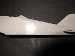
Along with a load of info sent by Vic, and some good colour pics off the 'net, I've been able to crack on and start adding detail to this rather basic kit.
First though, the moulded in roundel and numbers were removed from the fuselage, tail and wings, and ejector pin marks eliminated.
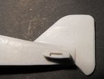
PICS 1 and 2 show the fuselage and tail after filing and sanding, and during polishing.
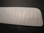
PIC 3 shows the wing during filing and sanding, since polished and any lost detail replaced.
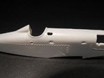
Next step was to drill holes where required, then start to add some basic detail to the cockpit, before modifying the seat and starting work on the main instrument panel.
PIC 4. A hole was drilled in the starboard cockpit wall, where the magneto hand crank fits, and the small window above the instrument panel was drilled out and filed to shape, the work still underway in this pic.
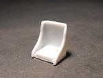
PIC 5. The seat as provided in the kit.
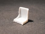
PIC 6. And after modification.
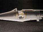
PIC 7. The port cockpit wall, showing the added frames and the mounting for the throttle (top) and the tail plane incidence adjusting wheel. The throttle lever and operating rod will be added after painting.
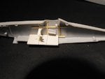
PIC 8. Starboard cockpit, with the frames, floor, mount for the rudder bar and hole for the control column, magneto housing at top, and the curved, lower section of the instrument panel.
The main panel is currently under construction, and should be finished soon.
Thanks for your interest and kind comments, and I'll post some more pics hopefully within the next few days.
Along with a load of info sent by Vic, and some good colour pics off the 'net, I've been able to crack on and start adding detail to this rather basic kit.
First though, the moulded in roundel and numbers were removed from the fuselage, tail and wings, and ejector pin marks eliminated.
PICS 1 and 2 show the fuselage and tail after filing and sanding, and during polishing.
PIC 3 shows the wing during filing and sanding, since polished and any lost detail replaced.
Next step was to drill holes where required, then start to add some basic detail to the cockpit, before modifying the seat and starting work on the main instrument panel.
PIC 4. A hole was drilled in the starboard cockpit wall, where the magneto hand crank fits, and the small window above the instrument panel was drilled out and filed to shape, the work still underway in this pic.
PIC 5. The seat as provided in the kit.
PIC 6. And after modification.
PIC 7. The port cockpit wall, showing the added frames and the mounting for the throttle (top) and the tail plane incidence adjusting wheel. The throttle lever and operating rod will be added after painting.
PIC 8. Starboard cockpit, with the frames, floor, mount for the rudder bar and hole for the control column, magneto housing at top, and the curved, lower section of the instrument panel.
The main panel is currently under construction, and should be finished soon.
Thanks for your interest and kind comments, and I'll post some more pics hopefully within the next few days.
Attachments
-
 SE5 build 010.jpg47.7 KB · Views: 60
 -
 SE5 build 012.jpg50.1 KB · Views: 59
 -
 SE5 build 016.jpg42.2 KB · Views: 69
 -
 SE5 build 019.jpg35.1 KB · Views: 60
 -
 SE5 build 021.jpg52.2 KB · Views: 60
 -
 SE5 build 023.jpg54.5 KB · Views: 59
 -
 SE5 build 036.jpg37.5 KB · Views: 62
 -
 SE5 build 037.jpg38.1 KB · Views: 59
vikingBerserker
Lieutenant General
Nice!
T Bolt
Colonel
Looking good Terry!
Vic Balshaw
Major General
I can see there is going to be no holding you back on this one old chap. Carry on.
- Thread starter
- #178
Airframes
Benevolens Magister
Thanks guys. Received some more pics from Karl, showing the RAF Museum's aircraft. Confirms that the housing for the Vickers gun needs modification - b*gg*r !
Crimea_River
Marshal
Looking good Terry.
Catch22
Major
Nice stuff.
Users who are viewing this thread
Total: 1 (members: 0, guests: 1)