Super detailing Guillow's P-51D Mustang

Ad: This forum contains affiliate links to products on Amazon and eBay. More information in Terms and rules

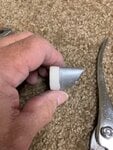
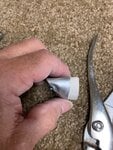
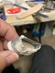
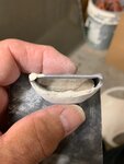
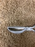
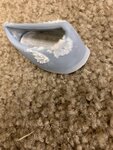
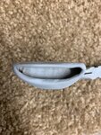
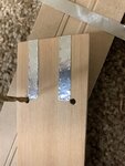
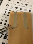
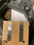
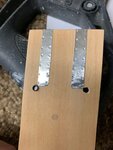
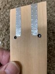
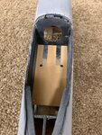
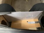
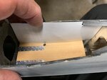
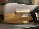
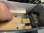
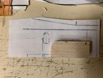
Here are the right and left profiles of the plastic inlet after I applied the heat and used a pair of pliers. As you can see, it was nearly impossible for me to maintain a slanted profile of the inlet with a thin plastic strip wrapped around the main body of the inlet.
 

Attachments

  • P-51 belly scoop -model # 65.jpg
    P-51 belly scoop -model # 65.jpg
    521.2 KB · Views: 65
  • P-51 belly scoop -model # 66.jpg
    P-51 belly scoop -model # 66.jpg
    451.2 KB · Views: 63
Application of Spackling filler was now applied.

The crack was also covered.
 

Attachments

  • P-51 belly scoop -model # 67.jpg
    P-51 belly scoop -model # 67.jpg
    335.3 KB · Views: 78
  • P-51 belly scoop -model # 69.jpg
    P-51 belly scoop -model # 69.jpg
    338.2 KB · Views: 94
After the filler dried. I sanded it down as smooth as possible and used several small files (rat tails) and cut up small strips of sandpaper to help sand away some of the more difficult areas. Not too bad. Still, there was a small defect on the right lip.
 

Attachments

  • P-51 belly scoop -model # 72.jpg
    P-51 belly scoop -model # 72.jpg
    952.1 KB · Views: 61
Some cutting with a hobby blade and more work with filler.

Sanded down the filler and then applied a coat of primer from a rattle spray can,

The primer was used to help see for any more defects.

Whereas not perfect, I think it's the best that I can do with what I have and my current skills.
 

Attachments

  • P-51 belly scoop -model # 57.jpg
    P-51 belly scoop -model # 57.jpg
    564.7 KB · Views: 66
  • P-51 belly scoop -model # 59.jpg
    P-51 belly scoop -model # 59.jpg
    390.7 KB · Views: 61
Wurger,

Excellent idea! I didn't think of using a solid block of plastic instead of wood. I think the plastic would have been a better medium to use.
 
Good evening gentlemen and fellow members:

I've progressed onward to the cockpit interior. It is my intention to have as many sub-assemblies finished as possible before moving on to both covering with the metal foil and the assembly of the major components. I figured that the interior is worth considering at this point of the build strictly as a matter of ease of accessibility to the interior without the wings and tail feathers bumping into my arms or vice versa.

As with all things on this Mustang build, I started out with some research. Some of which, you'll find this site as one of my sources. I trust all will be happy with some of the steps that I've taken thus far, and as always, all comments are welmed.

I thought I'd post this first picture. Whereas initially it looks very good and graphic in detail, I've found several errors. I'm curious if our fellow members can also point out to some of the differences. I'll start out by pointing out the location of the aileron trim wheel. In this illustration, it appears as if it's nearly vertical off the curved ramp of the side panel whereas in fact, it is located on the same plane as the rudder trim wheel.

I'm also enclosing the left side view as this is also the side I'm currently tackling now. As with most models in the 1/15th scale, there are not many aftermarket items readily available and thus, I'm making do with whatever I can find in arts and craft stores, laying about my home, or in the gardener's shed where the project is being built and lastly, my own imagination. I believe this is the left side of the full sized Mustang as looking closely, I can see the left side mounted on hinges as well as rollers at the bottom to help support the weight.

Finally, I've used computer graphics and drawings as helping me in determining the prospective locations of various cockpit controls.

I should point out that I'm really basically eyeballing everything and trying to keep things in proportion; meaning that it may not be measurably accurate, but proportionally speaking, looks good.
 

Attachments

  • P-51 cockpit interior # 3A.jpg
    P-51 cockpit interior # 3A.jpg
    79.9 KB · Views: 697
  • P-51 cockpit interior # 15A.png
    P-51 cockpit interior # 15A.png
    40 KB · Views: 118
  • P-51 cockpit interior CAD # 4A.png
    P-51 cockpit interior CAD # 4A.png
    23.5 KB · Views: 94
  • P-51 cockpit interior CAD # 3A.png
    P-51 cockpit interior CAD # 3A.png
    40.1 KB · Views: 97
I believe that a picture is worth a thousand words and in this case I'll try to take advantage of this and allow the photos to be self-explanatory. Only brief mention is the third photo in which it's barely noticeable that I'm holding the small plastic lens with the tweezers. These are for the fuel gauges on the wooden floor. I made the foot runners from the Flite Metal foil.
 

Attachments

  • P-51 cockpit -model floor # 7.jpg
    P-51 cockpit -model floor # 7.jpg
    456.8 KB · Views: 52
  • P-51 cockpit -model floor # 1.jpg
    P-51 cockpit -model floor # 1.jpg
    313.6 KB · Views: 54
  • P-51 cockpit -model floor # 6.jpg
    P-51 cockpit -model floor # 6.jpg
    494.2 KB · Views: 56
  • P-51 cockpit -model floor # 2.jpg
    P-51 cockpit -model floor # 2.jpg
    317.5 KB · Views: 71
Thank you Gnomey and Wurger,

Just as an aside, I'll probably be making some of my own custom instruments for the Mustang main instrument panel. For the sake of expediency, I am also using J-Tec Instruments. They come in a wide variety of sizes and styles and also has very good color saturation which I think will pay off mostly due to the small size of the instruments as well as having all that extra detailing.

I'm also going to (try) making my own stencils by making decals and having them reduced to size. Note, I mentioned sized and not scale as I'm really just eyeballing all of this to maintain what I believe is to be in correct proportion.
 
On pictures two and three, I messed up on the foot runners and the right side looked too wrinkled. So I peeled it off and made another one. The photo # 3 shows the revised metal running board.
 

Attachments

  • P-51 cockpit -model floor # 3.jpg
    P-51 cockpit -model floor # 3.jpg
    381.6 KB · Views: 52
  • P-51 cockpit -model floor # 4.jpg
    P-51 cockpit -model floor # 4.jpg
    406.1 KB · Views: 49
  • P-51 cockpit -model floor # 19.jpg
    P-51 cockpit -model floor # 19.jpg
    253.9 KB · Views: 74
  • P-51 cockpit -model floor # 20.jpg
    P-51 cockpit -model floor # 20.jpg
    518.6 KB · Views: 74
I'm now working on the left side. I trust that occasionally I'll repost the same photo to help keep our frame of mind on the detailing that follows. Here, I've used the left side picture as my primary reference for replicating the left side in model form. I transferred the side view strictly by eye and using some proportion as a means of determining the general location of various components to the left cockpit. I did this also because the Guillow's kit has its own size/scale and it is not compatible with any known P-51 cockpit in terms of correct measurements.

From the drawing, I carefully placed it inside the model cockpit for comparison and to see how the images on the drawing correlates with the fuel gauges and foot runners.

The last picture shows what I think will be a workable elevator trim wheel. I'm thinking of just slicing off the top of the electrical protector (as viewed upside down in this photo).
 

Attachments

  • P-51 cockpit interior # 15A.png
    P-51 cockpit interior # 15A.png
    40 KB · Views: 68
  • P-51 cockpit -model floor # 8.jpg
    P-51 cockpit -model floor # 8.jpg
    281 KB · Views: 53
  • P-51 cockpit -model floor # 21.jpg
    P-51 cockpit -model floor # 21.jpg
    236.2 KB · Views: 51
  • P-51 cockpit -model floor # 9.jpg
    P-51 cockpit -model floor # 9.jpg
    319.6 KB · Views: 62
At this point, I'd like to ask if anyone has any good drawings or photos of the right side panel. I'm trying to determine the initial background wall and having some difficulty in seeing through all that clutter. I also noticed that there appears to be some variances between different interiors with regards to vertical supports. Any help for the right side panel would be greatly appreciated.

This picture shows a blank piece of paper of the right side wall. The nose is to the left of the photo. Any references would be helpful.
 

Attachments

  • P-51 cockpit -model floor # 28.jpg
    P-51 cockpit -model floor # 28.jpg
    221.1 KB · Views: 51
Here, I've compared different thicknesses to account for the added details on the sides. I used a thin 1/16" thick sheet balsa as my reference. As you can see, it's going to be very close to the fuel gauges on the floor.

At least, from what pictures I've seen on the Internet, this is about right. Although this particular photo is not ideal, it's the closest one I can find that shows the side panels and the floor fuel gauges. Looking carefully, and the gauges can just be seen next to the left side panel immediately near the upper left corner of the pilot's seat.
 

Attachments

  • P-51 cockpit -model floor # 22.jpg
    P-51 cockpit -model floor # 22.jpg
    311.3 KB · Views: 161
  • P-51 cockpit -model floor # 15.jpg
    P-51 cockpit -model floor # 15.jpg
    254.2 KB · Views: 104
  • P-51 cockpit interior # 3A.jpg
    P-51 cockpit interior # 3A.jpg
    79.9 KB · Views: 2,541
Thank you Wurger!! I'll use both images and combine the two. They appear both the same and slightly different. This was the main cause of my confusion. I'll go with the to;p image first to get the basic wall and then the bottom picture for the radio equipment.

Thank you!!
 
I decided to start with the left main side panel and go from there. I'm using a 1/8" thick balsa cutting the corner and sanding to shape. Then I compare the balsa block with my drawn image.
 

Attachments

  • P-51 cockpit -model floor # 10.jpg
    P-51 cockpit -model floor # 10.jpg
    225.3 KB · Views: 59
  • P-51 cockpit -model floor # 16.jpg
    P-51 cockpit -model floor # 16.jpg
    304.4 KB · Views: 53
  • P-51 cockpit -model floor # 17.jpg
    P-51 cockpit -model floor # 17.jpg
    430.4 KB · Views: 49

Users who are viewing this thread

Back