Super detailing Guillow's P-51D Mustang

Ad: This forum contains affiliate links to products on Amazon and eBay. More information in Terms and rules

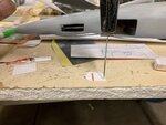
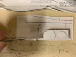
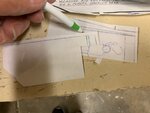
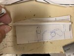
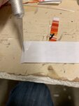
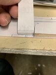
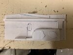
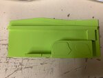
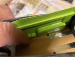
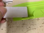
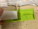
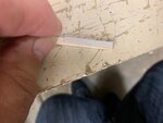
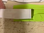
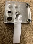
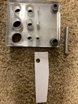
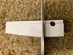
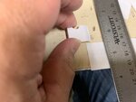
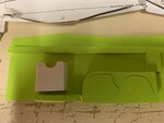
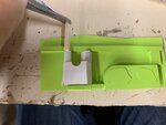
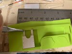
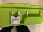
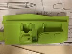
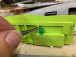
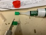
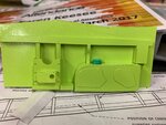
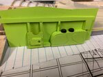
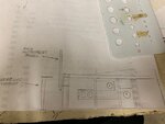
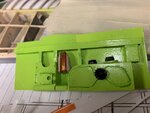
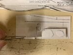
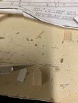
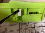
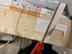
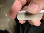
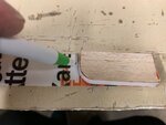
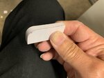
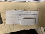
This is where using thin paper that is laminated with very thin plastic comes in handy. I wanted crisp sharp corners and flat, smooth consistent surfaces. Really simple and it works very well.
 

Attachments

  • P-51 cockpit -model floor # 18.jpg
    P-51 cockpit -model floor # 18.jpg
    235.7 KB · Views: 74
  • P-51 cockpit -model floor # 11.jpg
    P-51 cockpit -model floor # 11.jpg
    262 KB · Views: 71
  • P-51 cockpit -model floor # 12.jpg
    P-51 cockpit -model floor # 12.jpg
    226.7 KB · Views: 82
  • P-51 cockpit -model floor # 13.jpg
    P-51 cockpit -model floor # 13.jpg
    298.9 KB · Views: 74
  • P-51 cockpit -model floor # 14.jpg
    P-51 cockpit -model floor # 14.jpg
    306.4 KB · Views: 88
Last edited:
Thank you Wurger!! I'll use both images and combine the two. They appear both the same and slightly different. This was the main cause of my confusion. I'll go with the to;p image first to get the basic wall and then the bottom picture for the radio equipment.

Thank you!!

Here is a diagram of the starboard I found...

p51_a.jpg
 
The first picture shows me lightly hitting the "T" pin with a small hammer to place some 3-D rivets on the panels.
The next picture shows the panels with the rivets and glued onto the left side main quadrant
The remaining two images are pretty much self-explanatory as I'm slowly building up the left side. On the last picture, I purposely had the balsa stick partially shown to illustrate how I'm reinforcing the horizontal and vertical supports.
 

Attachments

  • P-51 cockpit -model floor # 38.jpg
    P-51 cockpit -model floor # 38.jpg
    312.2 KB · Views: 61
  • P-51 cockpit -model floor # 32.jpg
    P-51 cockpit -model floor # 32.jpg
    320.8 KB · Views: 70
  • P-51 cockpit -model floor # 39.jpg
    P-51 cockpit -model floor # 39.jpg
    214.5 KB · Views: 77
  • P-51 cockpit -model floor # 33.jpg
    P-51 cockpit -model floor # 33.jpg
    231.3 KB · Views: 63
Thank you again Wurger! I definitely could use the diagram of the left side. Really helps to clarify what needs to be done. As you can see what my approach is to the left side, so too, will be my approach to the right side. It's just the all the radio equipment was cluttering up what I needed to know about building up the back wall first before adding all of the accessories.
 
In my excitement, I decided to jump ahead of myself and paint the left side just to see what it will look like. By doing this too soon, I'm risking that the next accessories are not going to be easily stuck with glue to the paint. But oh well......
 

Attachments

  • P-51 cockpit -model floor # 37.jpg
    P-51 cockpit -model floor # 37.jpg
    260.3 KB · Views: 64
  • P-51 cockpit -model floor # 41.jpg
    P-51 cockpit -model floor # 41.jpg
    269.6 KB · Views: 66
  • P-51 cockpit -model floor # 35.jpg
    P-51 cockpit -model floor # 35.jpg
    255.3 KB · Views: 60
  • P-51 cockpit -model floor # 36.jpg
    P-51 cockpit -model floor # 36.jpg
    243.5 KB · Views: 74
The first picture shows that I have temporarily placed the whole left side panel into the cockpit area to see how close the side panels are to the fuel gauges on the floor. They're just about right.
The remaining pictures show how I'm eyeballing the paper/plastic with the horizontal railings to determine the height of the vertical supports and using balsa sticks as reinforcement.
 

Attachments

  • P-51 cockpit -model floor # 54.jpg
    P-51 cockpit -model floor # 54.jpg
    255.5 KB · Views: 60
  • P-51 cockpit -model floor # 51.jpg
    P-51 cockpit -model floor # 51.jpg
    251.6 KB · Views: 55
  • P-51 cockpit -model floor # 52.jpg
    P-51 cockpit -model floor # 52.jpg
    251 KB · Views: 57
  • P-51 cockpit -model floor # 47.jpg
    P-51 cockpit -model floor # 47.jpg
    294.1 KB · Views: 57
Last edited:
I'm now fabricating the "box" that is shown on the photos of the left side. I think my approach to creating the circular cutout is rather novel and straight forward with no guessing.
 

Attachments

  • P-51 cockpit -model floor # 55.jpg
    P-51 cockpit -model floor # 55.jpg
    213.3 KB · Views: 62
  • P-51 cockpit -model floor # 56.jpg
    P-51 cockpit -model floor # 56.jpg
    554.3 KB · Views: 73
  • P-51 cockpit -model floor # 57.jpg
    P-51 cockpit -model floor # 57.jpg
    663.5 KB · Views: 71
  • P-51 cockpit -model floor # 58.jpg
    P-51 cockpit -model floor # 58.jpg
    414.3 KB · Views: 62
We can easily see how the fabrication of the "box" is coming along.
 

Attachments

  • P-51 cockpit -model floor # 53.jpg
    P-51 cockpit -model floor # 53.jpg
    277.9 KB · Views: 57
  • P-51 cockpit -model floor # 50.jpg
    P-51 cockpit -model floor # 50.jpg
    223.7 KB · Views: 58
  • P-51 cockpit -model floor # 48.jpg
    P-51 cockpit -model floor # 48.jpg
    225.9 KB · Views: 59
  • P-51 cockpit -model floor # 46.jpg
    P-51 cockpit -model floor # 46.jpg
    230.2 KB · Views: 65
When comparing to the last picture of the full sized Mustang's left side, I'd say I'm coming along fairly well at this point using nothing more than household items such as paper/plastic, scissors, razor and some glue.
 

Attachments

  • P-51 cockpit -model floor # 45.jpg
    P-51 cockpit -model floor # 45.jpg
    225.9 KB · Views: 86
  • P-51 cockpit -model floor # 27.jpg
    P-51 cockpit -model floor # 27.jpg
    256.9 KB · Views: 85
  • P-51 cockpit interior # 15A.png
    P-51 cockpit interior # 15A.png
    40 KB · Views: 78
I now decided to try either fabricating or finding something closely resembling trim wheels for the rudder and ailerons. I discovered that, of all things, the ends of Krazy glue caps fit perfectly within the dimensions of the trim wheels. Not only that, but they also have small serrated edges that come close to the ridges of the trim wheels themselves. These serrated edges are smaller than scale even for this size, but I'm not complaining and it really helps. One only needs to look very closely at the small caps on pictures where I cut then and the small serrated edges can be seen

Later on, I will be fabricating the small "ramp" that supports the aileron trim wheel and gives it that "canted" look.

So, hopefully you can see my approach to replicating the left side will also serve me in my attempts to duplicate the right side as well. From there, I will tackle the main instrument panel and all of the instruments.

However, I thin my biggest challenge will be to try replicating all of those small stencils that surround the cockpit area. I believe this will truly make a difference. This is something new to me and it'll be my first attempt to add such small detailing at the level.
 

Attachments

  • P-51 cockpit -model floor # 43.jpg
    P-51 cockpit -model floor # 43.jpg
    211.8 KB · Views: 62
  • P-51 cockpit -model floor # 42.jpg
    P-51 cockpit -model floor # 42.jpg
    256.9 KB · Views: 72
  • P-51 cockpit -model floor # 44.jpg
    P-51 cockpit -model floor # 44.jpg
    369.1 KB · Views: 105
  • P-51 cockpit -model floor # 23.jpg
    P-51 cockpit -model floor # 23.jpg
    251 KB · Views: 73
Last edited:
Gentlemen:
Good afternoon. I'd like to start off by correcting my previous post # 248 on page 13. I posted a graphic illustration of a cockpit interior & mentioned that there were a few errors. I then listed the placement of the aileron trim wheel being located on a vertical portion of the left side panel when it should be flat alongside the rudder trim.

Not so! I discovered that the illustration was correct for the C variant of the Mustang which has its left side panel styled differently than the later D variants. I was just watching Kermit Week's video cam of flying his C Mustang when I saw the differences. My faux pas. Sorry guys.

Moving onward, I'll be working on both trying to come up with some decals of cockpit stenciling & the right side wall based upon the info provided to me through Wurger. Thank you, sir!
 
Crimea!! My good gracious! That Lope's Hope is incredible! I am also a member of Britmodeler & did t pay close enough attention to what was going on. I shamelessly asked for help. I don't know if I broke any protocols or such so I apologize in advance.
I also wish to extend my "Thank you, sir" for that reference. It's greatly appreciated!
 
Gentlemen,

Good evening and hoping all is well and in good health. I'm at this stage for the left side wall. I have a lot of extra detailing to do and will also submit additional posts along with respective photos to illustrate my progress to this point. However, I thought you would enjoy seeing where I'm standing now.

I've also submitted my drawings for the right side wall for your review. I used Wurger's designs, outlines, and various photos he generously supplied as references. I have to admit that I went through about three days trying to figured out which detail to include and which to leave out. This is only the preliminary stage and will be adding more detail as I progress. Please let me know what your thoughts are. It was rather difficult to filter out the accessories to get to the basic skeletal wall that is behind everything. Used a lot of eyeballing and some imagination. From there, I'll progress through some additional details and work on both sides at the same time.

Then I'll add the stencils. This is my challenge at the moment. Trying to come up with a feasible set of small logos, stencils and data plates in decal form. I wrote to one of the decal suppliers for Lope's Hope Mustang project that Crimea also generously provided. He was very nice and responded to my query about "one off's." Have to admit that Ray also requested that I provide him with all of the stenciling, at the correct scale and size before he will consider. Sounds to me as if I will do 85% of the work. Might as well go all the way.

Cheers,
 

Attachments

  • P-51 cockpit -model floor # 78A.jpg
    P-51 cockpit -model floor # 78A.jpg
    56.7 KB · Views: 53
  • P-51 cockpit -model floor # 63A.jpg
    P-51 cockpit -model floor # 63A.jpg
    42.9 KB · Views: 52
At this point, I thought it would be okay to compare the left side interior wall of the real Mustang with what I've accomplished so far. I have quite a long ways to go in detailing, but at least it's progress.

I'll be posting some of the details on how I managed to fabricate the elevator trim wheel and the small bag.
 

Attachments

  • P-51 cockpit interior # 15A.png
    P-51 cockpit interior # 15A.png
    40 KB · Views: 50
  • P-51 cockpit -model floor # 78A.jpg
    P-51 cockpit -model floor # 78A.jpg
    56.7 KB · Views: 51
Using my drawing as a starting point, I then transferred cutting up a small piece of glossy paper to help me reference the location and size of the bag to the left side wall. As with everything else, it was eyeballed...
 

Attachments

  • P-51 cockpit -model floor # 32A.jpg
    P-51 cockpit -model floor # 32A.jpg
    54.3 KB · Views: 39
  • P-51 cockpit -model floor # 31A.jpg
    P-51 cockpit -model floor # 31A.jpg
    44.4 KB · Views: 49
  • P-51 cockpit -model floor # 29A.jpg
    P-51 cockpit -model floor # 29A.jpg
    51.4 KB · Views: 41

Users who are viewing this thread

Back