Super detailing Guillow's P-51D Mustang

Ad: This forum contains affiliate links to products on Amazon and eBay. More information in Terms and rules

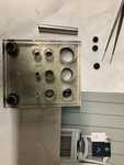
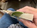
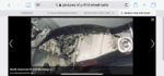
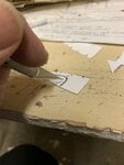
I used a punch-n-die set from MicroMark. They produce a wealth of model-specific tools and in this case, it came in good use.

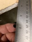
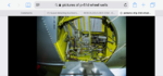
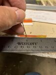
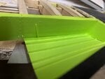
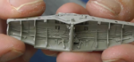
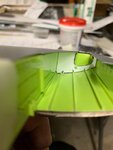
The last picture shows to good effect the size of the trim wheel I'm dealing.

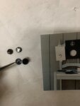
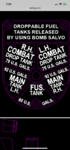
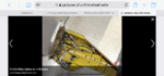
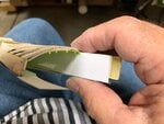
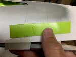
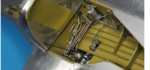
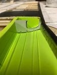
The middle photo shows what I'm trying to achieve. The paper of the small print is a bit too thick for the size of the trim wheel and I'll have to figure out a way to reduce the thickness or.... go the decal route. As everyone knows, printers in general, do not print out white. So, I figured perhaps they will print out the black background and leave the lettering alone. I haven't progressed to this stage yet and I'm asking for anyone's feedback or suggestions.
 

Attachments

  • P-51 cockpit -model 13.jpg
    P-51 cockpit -model 13.jpg
    291.7 KB · Views: 62
  • P-51 cockpit -model # 12.jpg
    P-51 cockpit -model # 12.jpg
    203.8 KB · Views: 63
  • P-51 cockpit model -instruments & trim # 1.jpg
    P-51 cockpit model -instruments & trim # 1.jpg
    595.3 KB · Views: 60
Good stuff.
I've been trying to get a micro punch and die set, but the only one that was available in the UK was the Waldron set, now discontinued. The Micro Mark set can be had from the US, but the cost of shipping, and then Import Duty, is prohibitive.

Printing the decals on white decal paper can work as a reverse image (i.e. black background and 'clear' lettering, or coloured lettering if needed), and I have done it in the past, in 1/48th scale, for a placard that measured about 5 x 3 mm. However, the resolution is not brilliant, due to the nature of inkjet, or even laser printer toner. It was passable enough for that particular need, but the lettering was not sharp, and was partly indecipherable.
It may work better reverse printing onto clear decal sheet - black background, clear letters - then placing the decal over a white painted surface, to give white lettering on a black background.
 
Wurger, Airframes, Gnomey, gentlemen,
Thank you for your comments. It's much appreciated. Glad you approve of my attempts to replicate the real instruments.

Airframes, I'll definitely try the printing and decaling both ways. If nothing else, I can always just leave the interior "as is" or resort to using the photos from the local shop. I'll keep you posted as I go along. In the meantime, I'd like to bring you up to speed on my other parts of the model while I was fiddling around with the instruments.
 
If anyone can reproduce the stenciling of the throttle quadrant, and any others it would be greatly appreciated. I've enclosed a couple of samples to give you an idea of what stenciling I'm looking for.
 

Attachments

  • P-51 cockpit interior CAD # 7.PNG
    P-51 cockpit interior CAD # 7.PNG
    64.3 KB · Views: 56
  • P-51 cockpit interior CAD # 2.PNG
    P-51 cockpit interior CAD # 2.PNG
    17.4 KB · Views: 55
Good evening gentlemen:
I reviewed my previous posts and wanted to make sure that I don't repeat myself. As mentioned before on page 15 post # 398, I tend to bounce around from one part of the model to another. This is another such example. I will gladly cover how I managed to frame up the interior right side of the cockpit interior in a moment, but I thought perhaps jumping back into the wheel wells would suffice. It's what I've been working on now anyway and everything is fresh on my mind.
 
Last edited:
I'm sure that as most detailed-oriented modelers will attest, that when building and detailing their models beyond what is called for in the kit or taking that extra step in detailing, that they constantly refer back to their sources of photos and documentation for references in ensuring accuracy, or at least the semblance of something close to it. In this case, I was reviewing the wheel well interiors and the main wing spar when I noticed that the main spar protrudes slightly from the backside of the wheel outline potion of the wheel well.

The first two photos are of the full sized Mustang D. The last photo shows that even the plastic models have this feature.

So, it was "back to the drawing board" and revise my plans and cut outs of the interiors.
 

Attachments

  • P-51 wheel well detail # 39A.png
    P-51 wheel well detail # 39A.png
    55.7 KB · Views: 73
  • P-51 wheel well detail # 40A.png
    P-51 wheel well detail # 40A.png
    51.9 KB · Views: 74
  • P-51 wheel well detail # 41A.png
    P-51 wheel well detail # 41A.png
    43.9 KB · Views: 69
I decided to tackle the wing spar and see where the balsa spar was located with respect to the wheel well outline. I quickly discovered that despite the added balsa strip, it was still too far back. It was then determined that a doubler would suffice in the form of a strip of 1/8" thick balsa. I also had to take into account for the thickness of the revised wing which included the rounded undersides and added thickness.

This is where the philosophy of knowing that when building "outside of the box" one must be prepared to revise their original plans and be flexible to meet the challenges. So it is in this case. The first photo shows I added an extra piece of balsa to the original spar to give it a bit of strength and added length to the original spar.
 

Attachments

  • P-51 wing spar # 7A.jpg
    P-51 wing spar # 7A.jpg
    42.7 KB · Views: 60
  • P-51 wing spar # 8A.jpg
    P-51 wing spar # 8A.jpg
    35.3 KB · Views: 58
I set about adding yet another strip of 1/8" thick balsa and also measured (eyeballed actually), the glossy paper laminate to cover the revised spar. I then flipped the paper upside down and used a pin to punch out some rivet patterns using a ruler for both as a straight edge and as a measuring guide.
 

Attachments

  • P-51 wing spar # 2A.jpg
    P-51 wing spar # 2A.jpg
    42.4 KB · Views: 43
  • P-51 wing spar # 4A.jpg
    P-51 wing spar # 4A.jpg
    46.8 KB · Views: 38
  • P-51 wing spar # 5A.jpg
    P-51 wing spar # 5A.jpg
    37.9 KB · Views: 44
  • P-51 wing spar # 1A.jpg
    P-51 wing spar # 1A.jpg
    53.7 KB · Views: 46
I then dressed up the paper laminate and spray painted it the ZC prior to gluing it to the additional balsa strip.

The "new" balsa spar laminate was then compared with the wheel well outline. This photo doesn't really show it to good effect, but the spar definitely "peeks" out from behind the wheel well outline. Future posts will reveal this in better form.

As you can see the interior is painted overall ZC. I respect Mr. Airframes' comment made way back on page 7 in which he said the during wartime, the only place in the wheel well interior that was painted ZC was the main spar. Only the freshly restored "modern-day" Mustangs featured the whole interiors sprayed with ZC. I knew I would be adding some plumbing to the interior and I felt a nice contrast between the silver tubes, electrical wiring or pipes and ZC background would help highlight the differences. So I trust Mr. Airframes will be alright with my decision.

Of course, now I've got to revise all of my ribs to new dimensions and start all over again. Such as it is, two steps forward and one step back.
 

Attachments

  • P-51 wing spar detail # 10A.jpg
    P-51 wing spar detail # 10A.jpg
    80.8 KB · Views: 39
  • P-51 wing spar detail # 11A.jpg
    P-51 wing spar detail # 11A.jpg
    37.3 KB · Views: 40
Last edited:
The "new" detailed spar installed in the right wing. If one were to compare the model to that of the real Mustang, there appears to be a vertical pattern of rivets along with what appears to be a metal strip mounted at a slant angle. I tried to replicate those features on the model spar.
 

Attachments

  • P-51 wheel well detail # 65A.jpg
    P-51 wheel well detail # 65A.jpg
    51.7 KB · Views: 51
  • P-51 wheel well detail # 66A.jpg
    P-51 wheel well detail # 66A.jpg
    37.2 KB · Views: 47
  • P-51 wheel well detail # 45A.png
    P-51 wheel well detail # 45A.png
    48.8 KB · Views: 51
  • P-51 wheel well detail # 46A.png
    P-51 wheel well detail # 46A.png
    43.7 KB · Views: 47
As if trying to detail the wheel well interiors was not enough, it was also discovered that there are a variety of interior wheel well detailing between "D" Mustangs. The photos are all of the wheel well interiors to the right wing of the "D" Mustang. They ranged from "minimalist" to the full blown wheel well with just about anything possible thrown in, as the last picture shows of one plastic kit manufacturer decided to make. I guess it was to "cover all the bases." and leave nothing to chance.

Now I've got a choice of interiors to choose from. Even the plastic models had their own interpretation of what a "D" interior wheel well should be.
 

Attachments

  • P-51 wheel well detail # 54A.png
    P-51 wheel well detail # 54A.png
    43.9 KB · Views: 59
  • P-51 wheel well detail # 109A.png
    P-51 wheel well detail # 109A.png
    45.7 KB · Views: 63
  • P-51 wheel well detail # 40A.png
    P-51 wheel well detail # 40A.png
    51.9 KB · Views: 67
  • P-51 wheel well detail # 93A.png
    P-51 wheel well detail # 93A.png
    78.7 KB · Views: 68
  • P-51 wheel well detail # 115A.png
    P-51 wheel well detail # 115A.png
    68.5 KB · Views: 71
With no real actual photo documentation of Big Beautiful Doll itself to go by, I decided to detail the wheel well interiors using a mixture of wheel wells from different aircraft that I thought would look good. I chose this one from the full sized Mustang. I just liked the orderly way the plumbing was arranged in parallel, combined with the "usual" twisted bends and electrical wiring, and all contrasted with the ZC background. This is the primary reason why I opted for the overall green ZC background interior.

I could've gone the easy way and choose the "minimalist" interior with hardly any plumbing seen, but somehow it just didn't look right. So, the decision was made purely on subjective grounds. Call it "Artistic License" if you will.
 

Attachments

  • P-51 wheel well detail # 50A.png
    P-51 wheel well detail # 50A.png
    43.6 KB · Views: 49
Wurger. & Gnomey,
Thank you sirs. I realize that even with the model to be displayed over a mirror, it's all likelihood there would be very little for the viewer to see unless the model itself is turned upside down. I've seen several videos of competition models on display in a similar fashion & despite these circumstance the modeler would detail the interiors anyway.
 
As noted in my previous post # 311, I've had to resize all of my ribs to reflect the new dimensions between the inside of the leading edge and the 'new" spar. This required that I shorten the lengths (or chord) of the ribs yet still maintain the height and curvature such that the outer skin will follow through in a continuous manner. Does all that make sense? Anyway, here's some photos of my results. I cut out the "new" ribs and also cut out the openings. From there, I trial fitted each one to the wing to make sure they were of the correct length and also slotted to fit the stringers. Then I placed the faux wing skin over to double check the height and curvature before moving onto the next rib.
 

Attachments

  • P-51 wheel well detail # 72A.jpg
    P-51 wheel well detail # 72A.jpg
    41.2 KB · Views: 29
  • P-51 wheel well detail # 71A.jpg
    P-51 wheel well detail # 71A.jpg
    38.1 KB · Views: 31
  • P-51 wheel well detail # 70B.jpg
    P-51 wheel well detail # 70B.jpg
    36.4 KB · Views: 31

Users who are viewing this thread

Back