Super detailing Guillow's P-51D Mustang

Ad: This forum contains affiliate links to products on Amazon and eBay. More information in Terms and rules

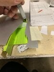
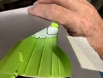
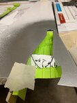
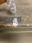
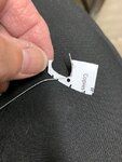
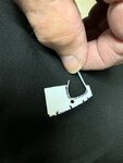
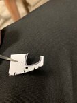
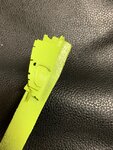
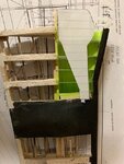
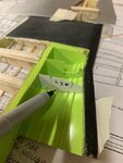
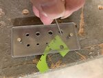
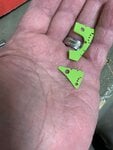
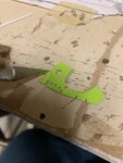
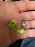
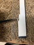
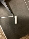
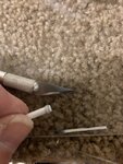
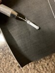
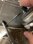
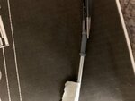
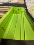
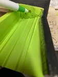
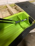
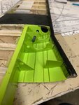
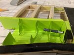
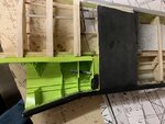
Here I'm taking another rib and having it trial-fitted for the slots over the stringers. I also placed the faux wing over the rib to help determine the cutout for the wheel well clearance to follow the exact outline of the wing.
 

Attachments

  • P-51 wheel well detail # 90A.jpg
    P-51 wheel well detail # 90A.jpg
    45.8 KB · Views: 36
  • P-51 wheel well detail # 89A.jpg
    P-51 wheel well detail # 89A.jpg
    38.7 KB · Views: 37
I repeated this step several times to the last rib. Each rib was measured (eyeballed) to ensure that the cutout conformed to the outline of the wheel well on the skin. This last rib actually is in two separate parts as seen in the full sized Mustang.
 

Attachments

  • P-51 wheel well detail # 91A.jpg
    P-51 wheel well detail # 91A.jpg
    44 KB · Views: 29
Using the small MicroMark punch-n-die set, I was able to punch out several holes into each rib. This photo was set up using extra scrap ribs to illustrate my techniques for making the holes. This punch-n-die set is very accurate and easy to use. No worries about cutting out tiny holes using a drill or razor. As you can see from the size of the set compared to my hands, its quite small. Very good to have for small accessories.
 

Attachments

  • P-51 wheel well detail # 88A.jpg
    P-51 wheel well detail # 88A.jpg
    72.4 KB · Views: 31
  • P-51 wheel well detail # 87A.jpg
    P-51 wheel well detail # 87A.jpg
    53.1 KB · Views: 37
I knew that the thin plastic would be too thin to both see direct head-on as well as not being realistic in duplicating the real ribs. So I added extra thin strips of plastic to the insides of the cutouts to give them both depth as well as a more realistic presentation of the ribs. I must admit that my eyes were a bit sore after staring for long lengths of time and working with tweezers. This was done on each rib for both wings. The entire process took me about a week.

On the last picture, if you zoom in and look closely, you can just see the tip of the small strip sticking out of the cutout. Later, I cut that one off.
 

Attachments

  • P-51 wheel well detail # 69A.jpg
    P-51 wheel well detail # 69A.jpg
    89.6 KB · Views: 32
  • P-51 wheel well detail # 75A.jpg
    P-51 wheel well detail # 75A.jpg
    72.7 KB · Views: 31
  • P-51 wheel well detail # 74A.jpg
    P-51 wheel well detail # 74A.jpg
    74.9 KB · Views: 31
A quick shot of paint. This rib was stuck on with tape rolled over itself to form a double-sided tape to hold the rib while spray painting.
 

Attachments

  • P-51 wheel well detail # 82A.jpg
    P-51 wheel well detail # 82A.jpg
    91.1 KB · Views: 33
I also made use of the landing gear cover as a guide for some of the cutouts as well. In the first picture, you can easily see how razor-thin the ribs are. The second picture shows the finished rib already glued in place. The thin strips of plastic within the cutout really helps to give it depth and dimension. I also had to make sure that each hole that was punched out was lined up with the previous rib such that the plumbing should rollow a straight line. Lots of thinking here.
 

Attachments

  • P-51 wheel well detail # 83A.jpg
    P-51 wheel well detail # 83A.jpg
    66.8 KB · Views: 35
  • P-51 wheel well detail # 84A.jpg
    P-51 wheel well detail # 84A.jpg
    74.8 KB · Views: 41
Here's a good close up of the punch-n-die set that allows me to produce such small holes.
 

Attachments

  • P-51 wheel well detail # 129A.jpg
    P-51 wheel well detail # 129A.jpg
    55.7 KB · Views: 30
The first picture shows the ribs in my hand. Looking closely, you can see at the very edge is a half-round cut out made by the punch-n-die set. The second picture shows me using a razor to cut a straight line from the two half-rounds.
The third photo shows the results. The rounded cuts really do not shows up well in this photo, but it shows what can be done to avoid having sharp cut corners. The purpose of the cutouts here to to allow room for the plumbing along the spar at back of the ribs.
 

Attachments

  • P-51 wheel well detail # 130A.jpg
    P-51 wheel well detail # 130A.jpg
    51.8 KB · Views: 34
  • P-51 wheel well detail # 131A.jpg
    P-51 wheel well detail # 131A.jpg
    46.4 KB · Views: 33
  • P-51 wheel well detail # 132A.jpg
    P-51 wheel well detail # 132A.jpg
    39.8 KB · Views: 27
Last edited:
These are the small Evergreen plastic rods that I will be using for most of the plumbing lines. As you can see, they're quite small in diameter.
 

Attachments

  • P-51 wheel well detail # 97A.jpg
    P-51 wheel well detail # 97A.jpg
    49.7 KB · Views: 32
For the main landing gear actuator I cut out a plastic tube of approximate length and diameter for my stash of various tubes from Evergreen.
Then I cut thin strips of electra tape. The tape normally comes in black, but in this case I painted it white ahead of time.
The thin strips of tape where then wrapped around the tube, but set back just a little bit from the edge to give it that more realistic look of an actuator.
The assembly was then hollowed out using a pin vise to accept the smaller diameter tubing that will act as the arm to the piston.
The whole assembly was then given a quick spray of gray paint from my rattle can.
 

Attachments

  • P-51 wheel well detail # 121A.jpg
    P-51 wheel well detail # 121A.jpg
    97.6 KB · Views: 32
  • P-51 wheel well detail # 122A.jpg
    P-51 wheel well detail # 122A.jpg
    56.6 KB · Views: 27
  • P-51 wheel well detail # 123A.jpg
    P-51 wheel well detail # 123A.jpg
    85.2 KB · Views: 31
  • P-51 wheel well detail # 116A.jpg
    P-51 wheel well detail # 116A.jpg
    70.1 KB · Views: 35
  • P-51 wheel well detail # 117A.jpg
    P-51 wheel well detail # 117A.jpg
    58 KB · Views: 30
The smaller diameter tubing was cut to extra length to give me flexibility in determining its exact location. Then it was masked off and sprayed with silver paint from a rattle can.
 

Attachments

  • P-51 wheel well detail # 118A.jpg
    P-51 wheel well detail # 118A.jpg
    42.7 KB · Views: 31
Now the gluing of the ribs begins. I also used a pen to mark off where I wanted to paint that particular area a flat black.
This will be self-explanatory in the next post.
 

Attachments

  • P-51 wheel well detail # 119A.jpg
    P-51 wheel well detail # 119A.jpg
    37.3 KB · Views: 32
  • P-51 wheel well detail # 120A.jpg
    P-51 wheel well detail # 120A.jpg
    36.5 KB · Views: 29
I then glued in the actuator. As you can see, the flat black lends itself quite well. I think it would've look somewhat awkward to have the piston arm end at a green wall. This way, there's the illusion of the arm ending "somewhere connected to the landing gear in the darkness."

What I've gathered, actuator is at an angle.
 

Attachments

  • P-51 wheel well detail # 124.jpg
    P-51 wheel well detail # 124.jpg
    284.2 KB · Views: 37
  • P-51 wheel well detail # 125A.jpg
    P-51 wheel well detail # 125A.jpg
    56 KB · Views: 37
Very nice. Have you though of using silver solder for the plumbing? It will bend around corners much easier than plastic rod. In fact, I don't know how you can bend plastic rod easily.
 
Crimea,
Good morning & thank you for watching my posts & for your query. To tell you the truth, I never thought of using silver solder. Given the small scale of the model & even smaller details, does silver solder come in such small sizes? The Tiny diameter of plastic rods permit easy bending & I have used an old hair dryer to help facilitate such bends. Once cooled (cooked?) the rods tend to retain their shape. The thickness of these rods is about the equivalent of a "T" pin. I'll show you in my later posts & see if this helps.
Sincerely,
Gary (Skye)
 
At this point, I was satisfied with the landing gear actuator. Now I had to figure out how to install all that plumbing we see within the wheel well interiors.
 

Attachments

  • P-51 wheel well detail # 140A.jpg
    P-51 wheel well detail # 140A.jpg
    45.3 KB · Views: 32
  • P-51 wheel well detail # 128A.jpg
    P-51 wheel well detail # 128A.jpg
    100.2 KB · Views: 38

Users who are viewing this thread

Back