Super detailing Guillow's P-51D Mustang

Ad: This forum contains affiliate links to products on Amazon and eBay. More information in Terms and rules

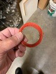
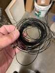
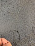
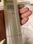
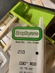
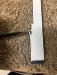
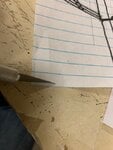
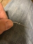
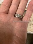
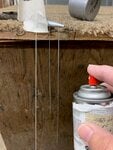
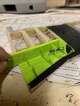
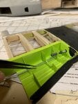
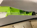
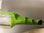
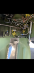
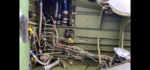
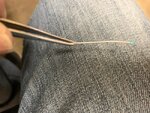
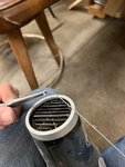
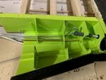
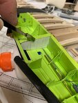
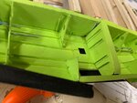
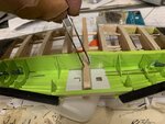
My initial thoughts were to use household wire. The type I found was relatively the size I was looking for. Plus, it bends very easy and retains that bend. I could shape it into complex patterns with ease. I also had plenty of this wire to do about four dozen wheel well interiors and then some. Just one itsy bitsy problem: Only needed to find a way to straighten it out. Upon unraveling the black colored wire, I tried every which way to straighten it out. I would cut a short length of wire, clamped one end to a vice and pulled it as straight as possible. Then I would roll it back and forth over a flat surface of the table. I came pretty close, but the kinks were still there no matter how much effort I put into it. Once the wire is bent, it would take an Act of Congress to get it straight. I had to figure out another way to simulate the plumbing.
 

Attachments

  • P-51 wheel well detail # 113A.jpg
    P-51 wheel well detail # 113A.jpg
    46 KB · Views: 35
  • P-51 wheel well detail # 112A.jpg
    P-51 wheel well detail # 112A.jpg
    59.6 KB · Views: 33
  • P-51 wheel well detail # 114A.jpg
    P-51 wheel well detail # 114A.jpg
    147.7 KB · Views: 29
Bingo! Problem solved.

The third picture shows the rods at approximately .030" or 0.75mm. Very small, almost like the size of a "T" pin. This would be the size necessary for me to thread the rods through the tiny holes of the ribs.
 

Attachments

  • P-51 wheel well detail # 126A.jpg
    P-51 wheel well detail # 126A.jpg
    44 KB · Views: 32
  • P-51 wheel well detail # 127A.jpg
    P-51 wheel well detail # 127A.jpg
    46.6 KB · Views: 36
  • P-51 wheel well detail # 97A.jpg
    P-51 wheel well detail # 97A.jpg
    49.7 KB · Views: 33
  • P-51 wheel well detail # 99A.jpg
    P-51 wheel well detail # 99A.jpg
    166.6 KB · Views: 34
Last edited:
Now that I have the sized plumbing needed, I only had to fabricate the connectors to the plumbing. At first, I tried my usual method of cutting thin strips of electrical tape, or even clear Scotch tape. Unfortunately, the electrical tape was far too thick and the clear tape was too sticky to use on such a small area without it folding over itself like a decal and causing a tangled mess.

I had a bright idea of using thin strips of ordinary notebook paper. Its thickness is very thin and I can cut it into thin strips. I used a razor over a flat surface and then super glued the end to one of the rods to test my idea. After the glue dried, I cut off the small tailing of the paper left over with the razor and wrapped the other end around twice. It worked.

I found if I only wrapped the thin strip of paper once, it doesn't really show up thick enough to pass for a connector. So, twice it is......

Crimea:
As you can see, the plastic rods are quite small in diameter. I do not know if silver solder comes in this size.
 

Attachments

  • P-51 wheel well detail # 121A.jpg
    P-51 wheel well detail # 121A.jpg
    97.6 KB · Views: 28
  • P-51 wheel well detail # 154A.jpg
    P-51 wheel well detail # 154A.jpg
    47.9 KB · Views: 33
  • P-51 wheel well detail # 155A.jpg
    P-51 wheel well detail # 155A.jpg
    93.5 KB · Views: 37
  • P-51 wheel well detail # 156A.jpg
    P-51 wheel well detail # 156A.jpg
    43.2 KB · Views: 30
I taped some weight on the ends to keep them from swaying against the spray from the paint. Then I spray painted them silver using my rattle can.
 

Attachments

  • P-51 wheel well detail # 111A.jpg
    P-51 wheel well detail # 111A.jpg
    94.6 KB · Views: 32
Good evening gentlemen and fellow guest:

Tonight I am opening a new build thread very similar to previous build threads ( See Guillow's S.E.5 and Guillow's Wright Flyer) in which I take a Guillow's wooden kit and build it beyond the stick-n-tissue format into a more realistic representation of the full sized aircraft. The exception here is that I'll be posting my builds "live" as I progress through the various stages rather than presenting a build thread with the model already completed. Thus, this thread will take several months to see the end result. However, the good news is I'll be open to ideas, suggestions, observations and any comments pertinent to the build itself and to the model. In another words, I would like to see some of our members actively particpate. I've decided to model this "D" Mustang as the later version of Big Beautiful Doll which depicts Col. Landers' plane as it racked up 36 victories. I have already contacted our esteemed fellow member, Mr. Wurger for information on BBD (as I'll abbreviate the name every once in awhile), and asked for his guidance as well as observations.

As of this writing, I have already framed up the wings and fuselage. However, they're not even close to being complete. They are still in the rough framed stage. I also just started on the vertical and horizontal tail feathers last night. They will be fabricated from sheets of solid balsa wood, rather than being framed up.

It's my intentions to model this aircraft in overall natural metal finish. Rather than taking the "usual" route of painting the model silver to represent the metal paneling, I've decided to really try something really different. I decided to use a product called Flite Metal. This product is an actual aluminum foil covering with a sticky adhesive backing. It comes in a roll that is 24" in width (I apologize for using the English measurements) and the length is cut per customer's needs/requirements (usually the minimum is about 10 feet). There are other products such as chrome vinyl that offer similar characteristics and I will gladly be posting the comparison between the two, siting their advantages and disadvantages and my choice for Flite Metal. Chrome vinyl is easily obtained through the Google search on the Internet. If anyone should express an interest in obtaining Flite Metal, I shall be happy to provide all of the relevant information. It is curently in production and the vendor is extremely active and supportive.

I will also be posting dozens of photos of each build stage as I progess along. Because photography in itself can slow down the build, I gave myself a "head start" in building the model and taking pictures through the build before opening up this post. This way, I'm hoping that I can give our fellow members a quick overall view of my concepts and approach to this build.

Some of you may ask "Why did I choose the Mustang?" And, "Why Big Beautiful Doll?" Truth be told, it is for my daughter. She insisted that if I'm to build her a model for her to keep as a family heirloom, she wanted a P-51D Mustang and finished off as BBD. She already has a full sized poster of the cockpit interior of BBD hanging up on the wall in her home. I tried to talk her out of it (Lord knows I tried) but she was adamant. So, without further ado, I'll start the posting tonight.
Sounds like a very interesting project!!!
 
Now the "fun" begins as I slide the thin plastic rods through the holes. At this point, I didn't glue them as I wasn't sure if everything was good. That, plus I knew I would have to perform complex bends at the opposite opening of the wheel well, which requires me to have access to the free end. In my next post, you'll see that there was also another reason I'm glad I didn't glue them in place.

In the meantime, with each additional rod, the wheel well interior really starts to look good.

I placed my faux skin over the wheel well to see how it would look

The last picture shows the wheel well interior looking straight down as most likely it will be presented, over a mirror. Thus, the landing gear actuator disappears. So, it means whoever looks at the model, will most likely have to seek the interior at a sideways glance to see the actuator. At least I got that far, even at the risk that it would never be seen.
 

Attachments

  • P-51 wheel well detail # 135A.jpg
    P-51 wheel well detail # 135A.jpg
    52.2 KB · Views: 44
  • P-51 wheel well detail # 136A.jpg
    P-51 wheel well detail # 136A.jpg
    54.1 KB · Views: 43
  • P-51 wheel well detail # 138A.jpg
    P-51 wheel well detail # 138A.jpg
    44 KB · Views: 42
  • P-51 wheel well detail # 139A.jpg
    P-51 wheel well detail # 139A.jpg
    47.9 KB · Views: 45
While I was pushing the rods into place and pulling them out, I started knocking off the ribs. Thus, I had to reinforce their placement with some extra "brackets." Here, this bracket is posed for the camera prior to painting. I had to first paint the brackets before installing them or else the spray paint would spread all over the interior no matter how much I would carefully mask off the area. I could probably use a paint brush but either way, at this point it wouldn't make much difference and I'd like to avoid brush marks as much as possible.

In the second picture, if you zoom up and look very closely, you can just see the brackets glued in place to help hold the thin ribs. It worked and I haven't had any issues since then. I was also happy to see that the super glue held the brackets in place despite being glued over paint. Just another issue that comes with building "outside of the box."
 

Attachments

  • P-51 wheel well detail # 137A.jpg
    P-51 wheel well detail # 137A.jpg
    53.3 KB · Views: 32
  • P-51 wheel well detail # 140A.jpg
    P-51 wheel well detail # 140A.jpg
    45.3 KB · Views: 27
Beartown550
Thank you sir. Glad to have you aboard. I have drawn much inspiration from a gentleman named "Peter" of Britmodeler.com who goes under the user name of "Ace." As of this writing, he's in the process of modeling a P-51C Mustang named "Lope's Hope." To me, he's taken modeling to new heights and have drawn much experience using photo-etched brass in his detailing.
 
Last edited:
What color to paint the connectors? Looking at dozens of wheel well interiors of restored Mustangs -the key here is: "restored," I decided on blue or a teal color. i figured a variety of colors, even if its just a spot here and there, will do much for the interior in addition to the ZC, brass, silver and black. I will also probably add some white, orange or red to the electric conduits and other colors as I go along. I guess you could call it "artistic license."

Soooo, teal or blue it is!
 

Attachments

  • P-51 wheel well detail # 106A.png
    P-51 wheel well detail # 106A.png
    64.2 KB · Views: 52
  • P-51 wheel well detail # 107A.png
    P-51 wheel well detail # 107A.png
    89.6 KB · Views: 50
  • P-51 wheel well detail # 171A.jpg
    P-51 wheel well detail # 171A.jpg
    110.4 KB · Views: 44
This is what I used to heat the plastic rods to help bend it into shape. I've found I could simply "cold" bend the plastic rods, but they tend to revert themselves back to (almost) their original shape. Believe it or not, this photo is exactly how I use the dryer. It's sitting on my lap, being held between my legs and thus, freeing my hands to bend the rod using needle nose pliers. Because the rods are so thin and small, I only have to hold the rods over the dryer for a few seconds.
 

Attachments

  • P-51 wheel well detail # 153A.jpg
    P-51 wheel well detail # 153A.jpg
    55.1 KB · Views: 37
Full disclosure: I have absolutely no idea as to how the landing gear actuator was plumbed. I looked over the Internet and within my own photo collection, books, magazines and could not find any references. So, I'm guessing how it's plumbed. I had observed many tractors, cranes, backhoes, and caterpillars with heavy blades and long hydraulic arms with rubber plumbing and figured the Mustang's landing gear struts must be plumbed in a similar manner. What the heck?

Mo' artistic license.... eh?

Here, I've placed one end of the thin rod next to the actuator to eyeball where I should start my next bend to the actuator itself.
 

Attachments

  • P-51 wheel well detail # 158A.jpg
    P-51 wheel well detail # 158A.jpg
    67.1 KB · Views: 34
From there, I bent the rod to a nice rounded curve to meet the actuator and then painted the connector ends prior to gluing in place. I purposely left the opposite end short for another connector and to allow for flexibility in giving me a chance to perform complex bends outside of the wheel well and then glue them into place with a connector in the middle..
 

Attachments

  • P-51 wheel well detail # 145A.jpg
    P-51 wheel well detail # 145A.jpg
    53.7 KB · Views: 35
  • P-51 wheel well detail # 159A.jpg
    P-51 wheel well detail # 159A.jpg
    78.2 KB · Views: 35
Crimea,
Good morning & thank you for watching my posts & for your query. To tell you the truth, I never thought of using silver solder. Given the small scale of the model & even smaller details, does silver solder come in such small sizes? The Tiny diameter of plastic rods permit easy bending & I have used an old hair dryer to help facilitate such bends. Once cooled (cooked?) the rods tend to retain their shape. The thickness of these rods is about the equivalent of a "T" pin. I'll show you in my later posts & see if this helps.
Sincerely,
Gary (Skye)

Gary, yes, I actually have found uses for it even in 1/48 scale, though I use fine lead wire for most applications. I was able to buy spools of resin core solder at a local electronics hardware store and I have two sizes. The smallest is 0.6mm diameter (.022") and the other one is 0.8mm (.032")

You are going much quicker than I can keep up but FWIW, here's a diagram of the undercarriage hydraulics, though your jack (item 6) is hard to see. Normally there would be a line into both ends of the cylinder (one on either side of the piston) and that's what this one has, though its hard to see.
Capture.JPG
 
Last edited:
Crimea,

I sincerely thank you, sir for your reply. I too, have small spools of wire about the sizes you described. I thought of using them as well. Only issue was trying to get them to lay down straight. I've posted my efforts at trying different ways to get the wires to straighten out, but to no avail.

II also wish to extend my gratitude for the drawing of the hydraulic system. It's greatly appreciated!! Mr. Wurger and yourself have contributed to helping me achieve more clarity in my efforts at detailing.

I also draw much inspiration from you, Wurger and Airframe's feedback. Thank you to each of you gentlemen.

Gary
 
This is the wheel well interior as it stands today. The extended rod in the middle is only temporary. I will be adding a "connector" to that point after the two wing panels are joined together and I can determine how much room I have along with the outlines of the wheel wells to help me in my "plumbing."

I also temporarily added the thin brass tubing to see how it looks. There's a wheel well on one of the full sized Mustangs with what appears to be brass colored tubing. However, this tubing is in a zigzag pattern and I felt to replicate that in model form would end up being too amateurish. I've seen other modelers replicate wrinkles on fabric of old biplanes and even though the modeler's efforts is recognized, the results looked odd in model form. It is with that in mind, I felt a straight brass colored tube would look better.

I'm also aware that I cannot possibly replicate all of the plumbing within both wells as on the full sized Mustangs. I'm sure there are other modelers out there who are fully capable of being able to do this. For the moment, I'll have to be content to know that I've done the best I can with my current skill levels and time. Since I discovered ( & posted ) that there are literally dozens of different wheel well interiors of the "D" series Mustangs, my excuse is I do not have any photos of the original wheel wells to Big Beautiful Doll..... (ahem). I know, I can see some of you rolling your eyes... LoL
 

Attachments

  • P-51 wheel well detail # 159A.jpg
    P-51 wheel well detail # 159A.jpg
    78.2 KB · Views: 30
I agree that it's not easy to get kinks and curves out of wire. That's why I like solder and lead wire. I simply roll them between a ruler and my cutting mat and they come out dead straight.
 
Crimea,
Thank you for your response. It's much appreciated. If everyone goes back to my previous post # 341, we can see that I tried my best with wire. Admittedly I didn't use solder wire because at the time I had no idea that solder wire would be available in different sizes. So I learned something new from this experience & I thank you for that.
 
Good evening gentlemen,

I'm going to jump ahead of myself to point out that I made a HUGE Boo Boo.
Hint: The pictures I'm about to show were NOT reversed to each other.
Second Hint: Yes, I corrected the issue immediately before any feelings of frustration and discouragement had a chance to set in and thereby allow the model to sit for days or even weeks.
Can anyone spot it? These images are of the center rib that divides the two wing panels and their respective wheel well interiors.

I posted a third picture to help give you an overall view of the wheel well detailing. Om this picture, it was before the mistake was made.
 

Attachments

  • P-51 wheel well detail # 192A.jpg
    P-51 wheel well detail # 192A.jpg
    60.8 KB · Views: 36
  • P-51 wheel well detail # 199A.jpg
    P-51 wheel well detail # 199A.jpg
    48.8 KB · Views: 38
  • P-51 wheel well detail # 163A.jpg
    P-51 wheel well detail # 163A.jpg
    91.1 KB · Views: 38
Last edited:
Thank you beartown550 for your acknowledgements. It's much appreciated, sir.
 

Users who are viewing this thread

Back