Super detailing Guillow's P-51D Mustang

Ad: This forum contains affiliate links to products on Amazon and eBay. More information in Terms and rules

Gentlemen,
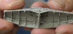
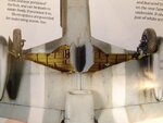
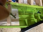
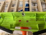
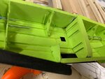
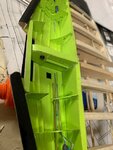
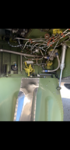
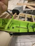
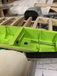
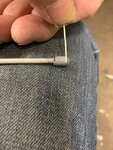
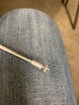
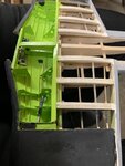
The time has finally arrived where I had to make a major decision and join the two wing panels together. I was concerned about adding too much (or too little) dihedral to the wings. At first, they appeared to be too low, but further references such as drawings and photos of the Mustang has showns my wing panels to be about right. The last picture on this post seem to bear this out.
Whew.

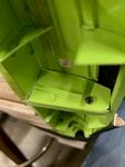
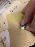
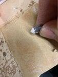
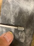
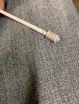
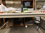
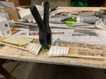
I used what we call here in the States, Gorilla Glue. That stuff is almost like a weld for all things nonmetallic. The properties of this glue.is such that it expands into small crevises and gaps as it dries. This is beneficial in a few ways: this is great for broken vases or objects that have scattered tiny pieces. The major components can be reassembled with the tiny pieces still missing and the glues fill in those gaps. It's also good for wood joints that are less than perfect and again, this glue will fill in those gaps. Thus, the instructions say to use this glue only sparingly as it can possibly crack the repair or join during its expansion. However, the trade off is that this glue really bonds and holds like a weld.

Boy, was I in for a surprise.
 

Attachments

  • P-51 wheel well detail # 161A.jpg
    P-51 wheel well detail # 161A.jpg
    65.6 KB · Views: 66
  • P-51 wheel well detail # 162A.jpg
    P-51 wheel well detail # 162A.jpg
    73.7 KB · Views: 73
  • P-51 overall viewA.png
    P-51 overall viewA.png
    77.8 KB · Views: 81
Last edited:
I put in some folded pieces of paper between the clamps and the wing spar so as to protect the finish from the teeth of the clamps. Well, the glue expanded alright. Right through whatever cracks it could find and into the paper. When the glue had completely cured, I had to peel off the paper from the spar. This is what's left. Now I have to figure out a way to camouflage this small discrepancy.

Still, it could've been worst.
 

Attachments

  • P-51 wheel well detail # 169A.jpg
    P-51 wheel well detail # 169A.jpg
    62.7 KB · Views: 55
In the absence of any detailed drawings or straight-on underside view of the full sized Mustang, I used a combination of models with partial views of the full sized aircraft to get a good idea of the overall plan view of the central interior. I noticed there were cutouts for the uplock and space near the leading edge of the wing that exposed larger plumbing.
 

Attachments

  • P-51 wheel well detail # 115A.png
    P-51 wheel well detail # 115A.png
    68.5 KB · Views: 63
  • P-51 wheel well & wing outlines # 51A.jpg
    P-51 wheel well & wing outlines # 51A.jpg
    53.3 KB · Views: 61
  • P-51 wheel well detail # 54A.png
    P-51 wheel well detail # 54A.png
    43.9 KB · Views: 60
  • P-51 wheel well detail # 56.PNG
    P-51 wheel well detail # 56.PNG
    177.2 KB · Views: 60
  • P-51 wheel well detail # 214A.png
    P-51 wheel well detail # 214A.png
    72.7 KB · Views: 72
  • P-51 wheel well detail # 215A.png
    P-51 wheel well detail # 215A.png
    76.7 KB · Views: 71
To this end, I set about cutting out a piece of thin plastic sheet about slightly oversized for the central area. From there, I eyeballed where the cutouts would go for the uplocks and the spaces for the large plumbing.
I then temporarily placed it over the wing and taped it down to give me a reference point to keep the lines of stringers in continuous length to the center main rib.

From there, I removed the plastic piece and completed the stringers outside of the wing as the interior area was too small for me hands, even with the use of tweezers.

I think I did a credible job of lining up almost all of the stringers. The exception was near the uplock cutouts.

From there, I spray painted the central assembly and set aside to dry
 

Attachments

  • P-51 wheel well detail # 165A.jpg
    P-51 wheel well detail # 165A.jpg
    81.9 KB · Views: 41
  • P-51 wheel well detail # 167A.jpg
    P-51 wheel well detail # 167A.jpg
    49.6 KB · Views: 38
  • P-51 wheel well detail # 168A.jpg
    P-51 wheel well detail # 168A.jpg
    50.9 KB · Views: 35
Ignoring the torn paper on the spar for the moment, I think the stringers were fairly lined up quite well.
 

Attachments

  • P-51 wheel well detail # 169A.jpg
    P-51 wheel well detail # 169A.jpg
    62.7 KB · Views: 44
  • P-51 wheel well detail # 199A.jpg
    P-51 wheel well detail # 199A.jpg
    48.8 KB · Views: 53
  • P-51 wheel well detail # 201A.jpg
    P-51 wheel well detail # 201A.jpg
    57.2 KB · Views: 58
Wurger, and Gnomey,,

Thank you gentlemen. I'll always appreciate your inputs.
 
Good evening (at least it's evening here on the west coast of U.S.A.). As I mentioned in my previous reply posting # 363 as well as showing the pictures, there were several variations of wheel well interiors; all of them on the "D" variant Mustang. Some featured fully restored Mustangs that were "better-than-new" with blue-colored connectors of various plumbing and near-sanitary white colored electrical conduits. However, all had some of the accessories in common. It was decided to include many of them within the Guillow's wheel well interiors.

Because of such a wide variety of different interiors, one would normally think it would be a nightmare. On the contrary, at least for me, it was a blessing. After the inclusion of the "mandatory" items such as the hydraulic reservoir, pressure gauge, large colored specific plumbing near the leading edge of the wings that was consistent with most of the "D" variants, I felt I had free reign to employ my own "artistic license" and allow my own creativity come into play. My "excuse" is I do not have any of the interiors specific to Big Beautiful Doll. Therefore, who's to judge?

Below, is a random sampling of the "mandatory" items mentioned previously and I felt they should be included. From there, it was "open season." The last item that I will install will be the landing light for obvious reasons of it being exposed.
 

Attachments

  • P-51 wheel well detail # 182A.jpg
    P-51 wheel well detail # 182A.jpg
    68.2 KB · Views: 34
  • P-51 wheel well detail # 107A.png
    P-51 wheel well detail # 107A.png
    89.6 KB · Views: 37
  • P-51 wheel well detail # 106A.png
    P-51 wheel well detail # 106A.png
    64.2 KB · Views: 39
To begin:
I thought it best to start with something rather large and use that as my reference point and go from there. As the full sized Mustang photo illustrates; I'm going to focus on fabricating the hydraulic reservoir. As you can see from the second photo, I've already cut out, glued a small ring obtained from a local fish and tackle store and installed it within the center rib. I took a picture and flipped it upside down to resemble that of the full sized article for comparative purposes.

As I was to later find out, my first attempt at fabricating the hydraulic reservoir ended up with the reservoir way too large.
 

Attachments

  • P-51 wheel well detail # 182A.jpg
    P-51 wheel well detail # 182A.jpg
    68.2 KB · Views: 40
  • P-51 wheel well detail # 198A.jpg
    P-51 wheel well detail # 198A.jpg
    69.1 KB · Views: 36
Before proceeding any further, I'd like to backtrack just a bit and show my approach to camouflaging the residue of the glue and paper from the main spar. I cut out a couple of small strips of plastic and had them painted the same color of ZC green as the overall interior. They were then folded and slipped and super glued into place. One would really have to zoom up carefully just to see them. Since everything is going to be upside down and inside the wheel well interiors, I very much doubt anyone would notice. I promise not to tell........
 

Attachments

  • P-51 wheel well detail # 235A.jpg
    P-51 wheel well detail # 235A.jpg
    82.3 KB · Views: 27
  • P-51 wheel well detail # 236.jpg
    P-51 wheel well detail # 236.jpg
    46.4 KB · Views: 32
To start with the hydraulic reservoir, I picked out what I thought is a suitable diameter plastic tubing and cut it to length that was roughly the same as what appears in the photo of the full sized Mustang's.

From there, I puttied a bit of compound and allowed to dry.

Then the whole was sanded slowly to the desired shape.
 

Attachments

  • P-51 wheel well detail # 202A.jpg
    P-51 wheel well detail # 202A.jpg
    50.8 KB · Views: 29
  • P-51 wheel well detail # 203A.jpg
    P-51 wheel well detail # 203A.jpg
    46.4 KB · Views: 31
Next, the tubing was fine-sanded to shape.

To give it that distinctive look of the ends, I cut up small strips of paper and super-glued just the tips to the tubing and allowed to dry.

Once dried, I then wrapped the strips around and glued the ends, leaving a small gap that resembles that of the full sized hydraulic reservoir.
 

Attachments

  • P-51 wheel well detail # 208A.jpg
    P-51 wheel well detail # 208A.jpg
    66.5 KB · Views: 27
  • P-51 wheel well detail # 209A.jpg
    P-51 wheel well detail # 209A.jpg
    93 KB · Views: 21
  • P-51 wheel well detail # 211A.jpg
    P-51 wheel well detail # 211A.jpg
    120.1 KB · Views: 23
Last edited:
To make the drain, I used the smallest plastic tubing from Evergreen I could find from my stash and drilled a hole using a pin vise. From there, I used the smallest plastic rod and cut it to size.

Next, the rod was inserted through the hole and glued in place.

Afterward, the whole sub assembly was glued on to bottom of the reservoir.
 

Attachments

  • P-51 wheel well detail # 204A.jpg
    P-51 wheel well detail # 204A.jpg
    110.9 KB · Views: 27
  • P-51 wheel well detail # 205.jpg
    P-51 wheel well detail # 205.jpg
    676.7 KB · Views: 25
  • P-51 wheel well detail # 206A.jpg
    P-51 wheel well detail # 206A.jpg
    93.9 KB · Views: 27
  • P-51 wheel well detail # 207A.jpg
    P-51 wheel well detail # 207A.jpg
    99.2 KB · Views: 32
This is a poor shot, as I was too embarrassed to photograph my mistake, but as you can see, despite all of my efforts of fabrication, the reservoir was too big. If you zoom up on the picture, you can see that the drain valve sticks out too far above the skin line. I tried cutting the top half off and refitting it, but it was still too big and awkward. So, I new, and smaller version was fabricated. It didn't have as much detail as the original as I didn't have the tools or supplies small enough to compensate, but it was still close enough.
 

Attachments

  • P-51 wheel well detail # 227A.jpg
    P-51 wheel well detail # 227A.jpg
    59.2 KB · Views: 33

Users who are viewing this thread

Back