Super detailing Guillow's P-51D Mustang (1 Viewer)

Ad: This forum contains affiliate links to products on Amazon and eBay. More information in Terms and rules

Kevin,

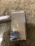
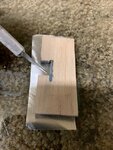
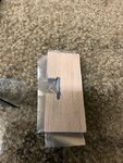
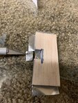
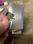
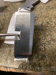
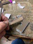
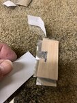
Thank you sir. I'm still very active in working on the model and will resume posting soon. I'm now at the stage where I've finished all the experimentation and now I need to practice on faux sections of the tail. I choice the tail area to be my first to cover with the foil and work my way forward.

I'll be posting the results of my practice sessions to show how I made some mistakes and learned from them before applying to the model. At least, the theory is that I hope to minimize any mistakes on the model.
 
Amazing attention to detail and pure craftsmanship. Years ago I started making a Curtiss 18-T from scratch (first flight was May 1918). I believe it was one of the first U.S. designed fighters as we were using British|French aircraft up to that time. I found a full set of 3-view drawings in one of my dad's old Flying magazines. Used calipers to measure fuselage frames, wings, braces, etc. The model was maybe 9-10 inches long. Since I could only get balsa wood in small thicknesses I had to bond several pieces together then carve out the fuselage and sand to shape. Had most of the big pieces made but the model got lost in a move. That was over 30 years ago and I still can't let it go!

Curtiss 18 triplane

Curtiss18T1.jpg
 
That's a really unique aircraft. Don't blame you for hanging on to it. Have you thought of making another model? Given the advancement of Internet & information is (almost) readily available at your fingertips, you should be able to access to 3-view drawings, complete with sections for fuselage & airfoils.

By the way, thank you for the compliment on my Mustang build. It's been a struggle trying to fabricate details from scratch as there are very little aftermarket accessories in that scale or for the Mustang in particular.

I have thought about making another model, it's just very low on my priority list and I had lost the 3-view drawings. Maybe after I retire. And you're right, the Curtiss 18 is very unique which is what drew me to it. Never knew before I found that, that the U.S. had ever made a triplane fighter.
 
Good evening to everyone. I trust that this posting will find all in good health and in (reasonably) good spirits, considering we're all pretty much confined to our domestic quarters for the duration, due to this Coronavirus. I have been busy working and experimenting on my P-51 and will continue posting for your entertainment and maybe, dare I say, for your amusement.
 
Good to know you're OK Gary, and looking forward to more up dates on the build.
I'm still working on the decals for you, albeit somewhat slowly, mainly due to my darned hands being so stiff, swollen and painful, and also still getting used to the changes involved with the Windows 10 update.
 
My previous post # 395 containing pictures of the wheel well interiors, is the last effort in this part of the model and I can safely say its concluded for the moment. I've moved on with two approaches: the cockpit interior and the foil covering. I chose the latter first as I was most anxious to see how I was experienced enough from my practicing to obtain satisfactory results. As you will see here, it's been a trial & error path to something of success. If I were to fail miserably, then I would simply finish off the cockpit interior, paint the whole model a silver color, add the decals and be done with it. But fortunately for both the model and myself, I was able to obtain a fair amount of good results.

For those of you who are just jumping onboard, this type of metal film covering is called Flite Metal and it's produced here in the U.S. It is best described as a highly polished aluminum foil that comes with a (very) sticky backing that is peeled off before applying to the surface.

I'm going to jump ahead of myself here, (something I've done frequently in the past) and show you the end results of my efforts. The reason for the jumping ahead is to show you my goals and objectives. The enclosed photos are of the horizontal stabilizer and elevator to the Mustang. This represents my third attempt.

The first picture shows the stab and elevator after my third effort and prior to adding some extra detail to the stab.

The second photo shows the same stab/elevator but with the addition of the small hatch on the top surface and the extra metallic covering over the leading edge. For both of these additions, I also marked the perimeters with a black ball point pen to help emphasize their place, as they tended to blend in with the surface.

In both pictures, you can easily discern I'm still a bit rough around the edges. This is truly a new skill that one must learn, practice and improvise through each stage. This is definitely not for the faint of heart.

At this point, I've decided to wait on the riveting detail as I've yet to cover the other side. However, you can easily see the riveting on the elevator. This was accomplished by the use of what we call "pounce wheel." I will be posting photos of my build and this tool in a bit later. Suffice to say, it resembles a pizza cutting wheel with serrated edges.
 

Attachments

  • P-51 tail feathers -model # 93A.jpg
    P-51 tail feathers -model # 93A.jpg
    47.5 KB · Views: 53
  • P-51 tail feathers -model # 94A.jpg
    P-51 tail feathers -model # 94A.jpg
    48.4 KB · Views: 49
Last edited:
Airframes,
Good hearing from you sir. Glad to hear you're still alive and well (at least well as we all can expect of each other). Great to hear the news.

Gary
 
Good evening gentlemen,

Tonight I'll start off by relating to you how I got to that stage of covering the horizontal stab with Flite Metal (a very thin sheet of aluminum foil with its own sticky backing that is peeled off).

As a preface, this Flite Metal, or sometimes referred to as FM for short, is a very good product. As noted at the beginning of my build thread, it is capable of withstanding up to 350 degrees before bubbling. This is far above what is expected of a film covering for a model. However, I also found out from the proprietor that his products is also used on full sized aircraft for different reasons.

The proprietor also noted that he has had several modelers complain about his product not being "good enough" or too difficult to apply, or did not live up to the advertisement of the finish they were expecting, and more. Between the both of us working together, we discovered that the vast majority of the complaints are from unskilled modelers who did not take the time to first read the detailed instructions that came with the product and did not take the time to fully understand how it is to be "worked on" and then applied.

I will state here and now, that this product is not for the faint of heart. If a person is not willing to learn a new skill or more importantly, have the patience, it is not for that person. It truly takes a lot of patience to acquire a new way of covering. It is not as easy as it looks on many brochures. As crazy as it may sound, it truly requires a new skill. Each person must find his/her way of applying the FM that works best. I've discovered a unique way that gives me the results that I'm looking for.

My goal is to create a scale model of a P-51 Mustang in a highly polished natural metal state as if it just rolled out the door after restoration and being lovingly cared for by its owner. I did not want that "authentic" WWII look of a warbird that has its metal worn out, or different panels of different shades of aluminum and so on. My goals were to be able to recreate this effect on a model. I realize that to many of you, this is not a representation of the full sized Mustangs that were used during WWII that shows the metal being worn, different shades of aluminum, some dents and scratches, oil stains and more. You would be correct. I chose this highly polished look for my own satisfaction and to see if this were possible, since its more difficult to achieve a perfect highly polished look without blemishes and defects. So the challenge for me, is a bit more.

The "worked on" portion of the application involves cutting a sheet of FM from the roll and taping it down to the table with a smooth top. I used a 1/4" thick plate glass as a smooth surface to work. The piece is stretched and taped on both ends. From there, I use a rubbing compound found in most auto-parts stores to " work" off the patina, or the surface of the aluminum that has been exposed to air and developed a coating that needs to be removed for that maximum shine. It this called oxidation. It occurs on almost all natural metals. This rubbing down also helps to soften the material for application.

I usually take this rubbing compound and apply it with a soft rag & rub it down until it dries. From there, I rub it off. The shine usually should show through. However, for me, I repeat this process at least another three times for maximum shine.

Okay, enough of my soapbox. On with my posts.... shall we?
 
Last edited:
To begin, I had no idea now much clearance would be needed between two surfaces between the stab and elevator. For this experiment, I decided to draw an outline that resembles the same outline of a typical stab/elevator hinge and balance horn. The FM would be first applied over the surface area and then folded over the edges. Its this folded over the edges is where I had no idea how much clearance to give.

The first picture shows me using a scrap sheet of 1/4" thick balsa.

The second picture shows why I decided on this hinge arrangement. It would give me the best idea of how much clearance would be needed.
 

Attachments

  • P-51 tail feathers -model # 41A.jpg
    P-51 tail feathers -model # 41A.jpg
    47.3 KB · Views: 32
  • P-51 tail feathers -model # 14A.jpg
    P-51 tail feathers -model # 14A.jpg
    68.5 KB · Views: 35
I decided to simulate as reasonably close to the ideal stab-elevator arrangement by cutting the balsa sheet, sanding the surfaces smooth, and finishing them off with primer. The first picture shows the # 400 black colored sand paper that was used to sand over the primer.

The second photo shows that I left a lot of room between the two surfaces to account for the folded aluminum foil
 

Attachments

  • P-51 tail feathers -model # 42A.jpg
    P-51 tail feathers -model # 42A.jpg
    89.2 KB · Views: 39
  • P-51 tail feathers -model # 43A.jpg
    P-51 tail feathers -model # 43A.jpg
    82.5 KB · Views: 32
I cut a small piece of FM from the roll and, as you can see, it's badly wrinkled from my clumsy handling. The sticky backing did not want to let go of my fingers. During my "battle" with the FM piece (I won), I ended up wrinkling the piece. I wasn't too concerned about the wrinkles as I was more focused on the clearance between the two surfaces.

This is an important note: I used bare wood at this point for photographic purposes. The second photo shows me using a soft rag to rub it down over the bare wood surface. Note here that the wood grain does not show through. This is good news for me as it would save me a lot of extra work in finishing off the surface of the wood in preparation for the FM. However, I was to pay a small price for this "convenience" as you will see.

The last photo shows the surface with small wrinkles and small bumps. The large dent is from the wood itself. I will use a burnishing tool to see if I can work out the small wrinkles and bumps.
 

Attachments

  • P-51 tail feathers -model # 26A.jpg
    P-51 tail feathers -model # 26A.jpg
    80.2 KB · Views: 32
  • P-51 tail feathers -model # 27A.jpg
    P-51 tail feathers -model # 27A.jpg
    55 KB · Views: 33
  • P-51 tail feathers -model # 29.jpg
    P-51 tail feathers -model # 29.jpg
    467.8 KB · Views: 31
After using the burnishing tool, I was able to work out the small bumps but not the wrinkles. A lesson for me to remember.

As part of my new skill set, I also had to be very careful handling the large roll of FM and be equally careful in cutting out the pieces I needed for covering. Just pulling the piece off the roll would create small wrinkles. I had to unroll by hand and allow the piece to hang off on its own before cutting.
 

Attachments

  • P-51 tail feathers -model # 29A.jpg
    P-51 tail feathers -model # 29A.jpg
    57.5 KB · Views: 33
After the piece was rubbed down, I used a pounce wheel to make simulated rivets.
This is where I realized the small price I had to pay for the "convenience" of not carefully finishing off the wood with varnish, or glue, or hardener (anything) that would harden the surface of the wood. As you can see, it really doesn't take much to product deep rivets that are grossly out of scale. The soft wood really showed me what happens. Now I know I'll have to very gently apply the pounce wheel and not use too much pressure.
 

Attachments

  • P-51 tail feathers -model # 30A.jpg
    P-51 tail feathers -model # 30A.jpg
    97.7 KB · Views: 35
  • P-51 tail feathers -model # 31A.jpg
    P-51 tail feathers -model # 31A.jpg
    69 KB · Views: 38
Okay, now it's time to practice on my faux hinge/balance piece. This time, the wood has been finished with primer, but no hardener.

The first picture shows the use of the burnishing tool to help rub define the outlines of the wood piece underneath

Using a fresh X-Acto blade I carefully cut away the unnecessary pieces of the Flite Metal to allow me to fold them over the edges.

I then carefully removed the cutout pieces
 

Attachments

  • P-51 tail feathers -model # 36A.jpg
    P-51 tail feathers -model # 36A.jpg
    74.7 KB · Views: 28
  • P-51 tail feathers -model # 37A.jpg
    P-51 tail feathers -model # 37A.jpg
    74.4 KB · Views: 30
  • P-51 tail feathers -model # 38A.jpg
    P-51 tail feathers -model # 38A.jpg
    88.1 KB · Views: 29
  • P-51 tail feathers -model # 40A.jpg
    P-51 tail feathers -model # 40A.jpg
    86 KB · Views: 26
I grabbed the larger excess and pulled it taut and downward along the edge of the balsa piece.

For the smaller areas, I used a pair of needle nose pliers to do the same thing to fold the FM along the inner cutouts.
 

Attachments

  • P-51 tail feathers -model # 33A.jpg
    P-51 tail feathers -model # 33A.jpg
    49.2 KB · Views: 28
  • P-51 tail feathers -model # 34A.jpg
    P-51 tail feathers -model # 34A.jpg
    66.4 KB · Views: 32
Boy that stuff is sure sticky! You can see the excess starting to wrinkle under my fingers.

Another lesson to learn.....
I used the backing paper that I peeled off to help me move the piece without it sticking to my fingers. A new skill set....
 

Attachments

  • P-51 tail feathers -model # 32A.jpg
    P-51 tail feathers -model # 32A.jpg
    70.4 KB · Views: 34
  • P-51 tail feathers -model # 39A.jpg
    P-51 tail feathers -model # 39A.jpg
    80.3 KB · Views: 30

Users who are viewing this thread

Back