Navigation
Install the app
How to install the app on iOS
Follow along with the video below to see how to install our site as a web app on your home screen.
Note: This feature may not be available in some browsers.
More options
You are using an out of date browser. It may not display this or other websites correctly.
You should upgrade or use an alternative browser.
You should upgrade or use an alternative browser.
Super detailing Guillow's P-51D Mustang
- Thread starter Skyediamonds
- Start date
Ad: This forum contains affiliate links to products on Amazon and eBay. More information in Terms and rules
More options
Who Replied?- Thread starter
- #442
Skyediamonds
Staff Sergeant
- 1,362
- May 26, 2018
Yes sir, my wife & family & extended families through our grown children are doing well. My daughter is a surgical nurse practitioner & she's extremely mad at our president & concerned for our welfare.
Nicely done so far!
- Thread starter
- #445
Skyediamonds
Staff Sergeant
- 1,362
- May 26, 2018
Thank you Gnomey, sir. It's much appreciated.
Gary
Gary
- Thread starter
- #446
Skyediamonds
Staff Sergeant
- 1,362
- May 26, 2018
Wurger,
By any chance, could you send me (again) the serial numbers to Big Beautiful Doll? This is the last version that was flown by Lt. Col. John Landers. I'm going to try to make up some of my own stencils and one of them will be appearing on the left side of the fuselage identifying it as: P-51D-5NA...... then it goes on to give pilot weight and etc.
By any chance, could you send me (again) the serial numbers to Big Beautiful Doll? This is the last version that was flown by Lt. Col. John Landers. I'm going to try to make up some of my own stencils and one of them will be appearing on the left side of the fuselage identifying it as: P-51D-5NA...... then it goes on to give pilot weight and etc.
- Thread starter
- #447
Skyediamonds
Staff Sergeant
- 1,362
- May 26, 2018
Good day to one and all.
I've been quite busy lately. The model is progressing rather slowly only due to the time-consuming task of producing the many cockpit interior stencils. The model is progressing on a linear path. That is, to say, each major component is dependent upon the preceding project being completed first before moving onto the next phase. The Flite Metal foil covering is extremely fragile. Even after a generous coat of clear paint or lacquer coating, it is (still) very susceptible to scratches, dings and the usual hangar rash associated with handling the model. That being said, it means the whole model, save for some accessories as landing gears, drop tanks (if built), propeller, hatches, cockpit interior, forward windshield and machine guns in the open bay, must be completed prior to adding any foil covering. This is to ensure a reasonable chance of minimal handling of the model. I suppose I should finish the landing gears first, se we'll see.
The detailing of the cockpit interior falls into this category. I have already handled this model in any which way possible trying to cut, fit, resize, and fit again the various accessories that make up the interior. I have stopped at the semi-completion of the left and right sides due to both needing radio equipment which in turn, needs additional details and of course......stencils. Hence, my original opening statement about stencils.
Traditionally speaking, I'll be jumping ahead of myself and quickly reveal some of the stencils completed so far on this post.
I do wish to add, that I am not without a bit of humor and decided to employ a little bit of "artistic license" to the stenciling project. After all, the Mustang will eventually be given to my daughter. Soooo, what else can a loving father do?
Attachments
- Thread starter
- #448
Skyediamonds
Staff Sergeant
- 1,362
- May 26, 2018
I was fortunate to save the images from someone who, in addition to the overall cockpit interior itself, was generous to post several cockpit stencils of the Mustang on this site. It was from this site that I borrowed many of the images used to produce the stencils as well as referring to several photos on the Internet.
The laptop wasn't "talking" to my printer so I was forced to fabricate my own stencils from tape, paper and dry transfer letters obtained from a local arts and crafts store. The lettering from the landing gear stencils were blurry so I had to "translate" them into my own stencils.
The laptop wasn't "talking" to my printer so I was forced to fabricate my own stencils from tape, paper and dry transfer letters obtained from a local arts and crafts store. The lettering from the landing gear stencils were blurry so I had to "translate" them into my own stencils.
Attachments


- Thread starter
- #449
Skyediamonds
Staff Sergeant
- 1,362
- May 26, 2018
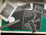
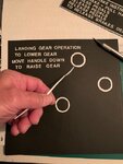
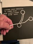
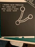
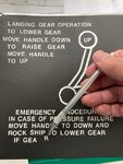
To lend a perspective of the amount of work involved, or more accurately, set myself up for.... I have posted a series of photos showing the step-by-step process for creating the stencil for landing gear operation instructions. What I found amazing, as you can see from my previous post of the image, is this particular stencil is located near the floor of the cockpit to the left of the pilot's ankle. I tried to imagine how this poor pilot wearing full uniform and flight gear, parachute, and perhaps his/her Mae West life preserver would try to double over one's self to read the instructions on gear operation near his/her left ankle.
Anyway, I started out with cutouts from pieces of paper for the circles using a compass as a guide and a X-Acto blade. From there, I painted black electrical tape an off-white color. Then I cut up the tape into thin strips. Why electrical tape? Simple, its very flexible allowing me to bend it at the "elbow" of the drawing.
Then it was off to using the white-colored dry transfer letters each letter at a time. Carefully lining them up to ensure a reasonable amount of accuracy.
Attachments
- Thread starter
- #450
Skyediamonds
Staff Sergeant
- 1,362
- May 26, 2018
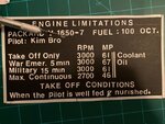
As mentioned previously, I did managed to squeeze in a bit of humor into my artistic license. Since this model will eventually be given to my daughter for display, I felt it only reasonable to include a little bit of fatherly humor. The engine limitation chart is to be posted on the upper right-hand side of the cockpit wall near the canopy rail for all to see. Thus, I "slightly" altered the engine limitations chart to suit the occasion. Can anyone spot the difference?
Attachments
syscom3
Pacific Historian
Thats great!As mentioned previously, I did managed to squeeze in a bit of humor into my artistic license. Since this model will eventually be given to my daughter for display, I felt it only reasonable to include a little bit of fatherly humor. The engine limitation chart is to be posted on the upper right-hand side of the cockpit wall near the canopy rail for all to see. Thus, I "slightly" altered the engine limitations chart to suit the occasion. Can anyone spot the difference?
- Thread starter
- #452
Skyediamonds
Staff Sergeant
- 1,362
- May 26, 2018
syscom,
Thank you very much.
I did make a slight (real) mistake and misspelled "Nurished." It should have been properly spelled "Nourished." Sooo, I immediately corrected my error and now my little humorous "artistic license" is in full effect.
My work on the stencils continue. What's Life without humor? I haven't told anyone else within my family and so the secret lies with us. I'll see what the reaction is, when given to my daughter.
Airframes
Benevolens Magister
Great stuff Gary. A long process, but well worth the effort.
My attempts continued, but I, too, was having printer problems, mainly ink feed.
Got a new cartridge, which improved things, but the resolution was still not very good when tried on decal papers. I'm glad to see you've had more success.
My attempts continued, but I, too, was having printer problems, mainly ink feed.
Got a new cartridge, which improved things, but the resolution was still not very good when tried on decal papers. I'm glad to see you've had more success.
- Thread starter
- #455
Skyediamonds
Staff Sergeant
- 1,362
- May 26, 2018
Airframes:
Good morning & good hearing from you. Happy to know you're doing good. No problems. Just knowing you tried was good enough for me. Still, I have a ways to go. To get around my printer issues, I'll be taking photos of my stencils from a distance that I think will be close to scale. Instead of taking a picture of a stencil from three feet, I'll probably take the photo at around ten feet distance or even more. That way, the size of the image is reduced. Then I take the roll of film to a local shop & have the pictures developed. From the prints, I'll simply cut them out & have the stencils pasted. These stencils are mostly images of data plates made out of metal, so (theoretically) the thickness of the paper from the print should not be an issue. As for the other stencils? Well, I've got a few tricks up my sleeve.
Gary
Good work so far!
- Thread starter
- #457
Skyediamonds
Staff Sergeant
- 1,362
- May 26, 2018
Gnomey,
Thank you, sir.
Thank you, sir.
- Thread starter
- #458
Skyediamonds
Staff Sergeant
- 1,362
- May 26, 2018
Wurger,
By any chance do you have the serial numbers to Lt. Col. John Lander's late Mustang?
By any chance do you have the serial numbers to Lt. Col. John Lander's late Mustang?
- Thread starter
- #459
Skyediamonds
Staff Sergeant
- 1,362
- May 26, 2018
Good evening gentlemen,
Discovered GeeDee's cockpit of the Mustang made quite a showing. Great job! Had no idea until recently that there would be a great source of information almost next door.
Discovered GeeDee's cockpit of the Mustang made quite a showing. Great job! Had no idea until recently that there would be a great source of information almost next door.
- Thread starter
- #460
Skyediamonds
Staff Sergeant
- 1,362
- May 26, 2018
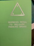
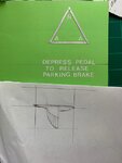
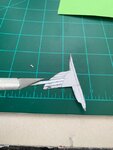
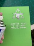
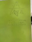
Made a little bit more progress the past few days. I focused on the rudder pedals. I used some tape cut up into thin strips for the triangle and for the eagle feathers. The letter were from the same dry transfer sheet used for the stencils and data plates.
I originally painted the image of the rudder pedal a darker shade of green as seen on the real aircraft. But the tone of the green was too dark for the logo to be seen and I'm sure it would disappear altogether when reduced to scale and placed deep down inside the cockpit. So I took a bit of artistic license and painted them the "usual" zinc chromate green I've been using for the wheel wells and cockpit interior.
I originally painted the image of the rudder pedal a darker shade of green as seen on the real aircraft. But the tone of the green was too dark for the logo to be seen and I'm sure it would disappear altogether when reduced to scale and placed deep down inside the cockpit. So I took a bit of artistic license and painted them the "usual" zinc chromate green I've been using for the wheel wells and cockpit interior.
Attachments
-
 P-51 Rudder pedals -model # 2A.png99.7 KB · Views: 66
 -
 P-51 Rudder pedals -model # 3A.jpg32 KB · Views: 67
 -
 P-51 Rudder pedals -model # 4A.jpg42.6 KB · Views: 63
 -
 P-51 Rudder pedals -model # 5A.jpg46 KB · Views: 69
 -
 P-51 Rudder pedals -model # 6A.jpg41.5 KB · Views: 71
 -
 P-51 Rudder pedals -model # 1A.jpg45 KB · Views: 66
Users who are viewing this thread
Total: 1 (members: 0, guests: 1)