Super detailing Guillow's P-51D Mustang

Ad: This forum contains affiliate links to products on Amazon and eBay. More information in Terms and rules

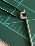
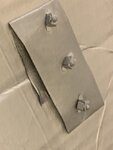
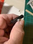
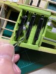
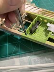
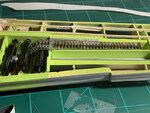
The next series of steps will illustrate the fabrication and installation of the solenoid firing mechanism. This was part of my reason why I posted the question in my previous postings as to "... What is that silver colored object mounted on the right side?"

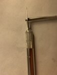
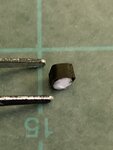
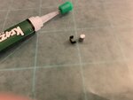
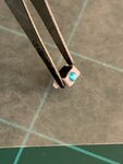
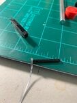
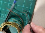
A plastic tubing was cut into a thin slice.
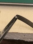
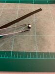
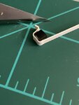
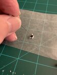
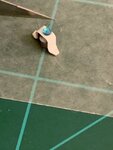
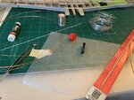
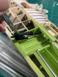
A black colored plastic strip was then cut and bent with a pair of tweezers into the first corner.
From there it was sized up to determine the remaining length and then cut. with an X-Acto # 11 blade
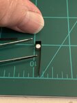
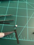
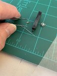
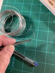
I purposely allowed my hands into the photo to help give scale to the small assembly
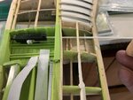
 

Attachments

  • P-51 machine guns & bay # 21.jpeg
    P-51 machine guns & bay # 21.jpeg
    27.3 KB · Views: 39
  • P-51 machine gun solenoid # 1.jpeg
    P-51 machine gun solenoid # 1.jpeg
    49.8 KB · Views: 35
  • P-51 machine gun solenoid # 3.jpeg
    P-51 machine gun solenoid # 3.jpeg
    35.3 KB · Views: 39
  • P-51 machine gun solenoid # 4.jpeg
    P-51 machine gun solenoid # 4.jpeg
    36.3 KB · Views: 41
  • P-51 machine gun solenoid # 5.jpeg
    P-51 machine gun solenoid # 5.jpeg
    39.6 KB · Views: 38
Here I'm adding some plastic strips around the initial assembly in effort to closely resemble the solenoid.
 

Attachments

  • P-51 machine gun solenoid # 6.jpeg
    P-51 machine gun solenoid # 6.jpeg
    46.3 KB · Views: 44
  • P-51 machine gun solenoid # 7.jpeg
    P-51 machine gun solenoid # 7.jpeg
    34.2 KB · Views: 40
  • P-51 machine gun solenoid # 8.jpeg
    P-51 machine gun solenoid # 8.jpeg
    39 KB · Views: 44
  • P-51 machine gun solenoid # 9.jpeg
    P-51 machine gun solenoid # 9.jpeg
    47 KB · Views: 41
  • P-51 machine gun solenoid # 10.jpeg
    P-51 machine gun solenoid # 10.jpeg
    38.7 KB · Views: 43
Sometimes it pays to have bits of babble from the local arts and crafts store. At first, I thought it would be too large, but after spray painting silver, things turned out alright.

As it turned out, I would only need one solenoid. The rest will be. hidden under the machine gun chutes. So at this point, I simply picked out what I thought the best of t he lot.
 

Attachments

  • P-51 machine gun solenoid # 11.jpeg
    P-51 machine gun solenoid # 11.jpeg
    50.2 KB · Views: 45
  • P-51 machine gun solenoid # 12.jpeg
    P-51 machine gun solenoid # 12.jpeg
    47.2 KB · Views: 46
  • P-51 machine gun solenoid # 13.jpeg
    P-51 machine gun solenoid # 13.jpeg
    48.2 KB · Views: 48
  • P-51 machine gun solenoid # 14.jpeg
    P-51 machine gun solenoid # 14.jpeg
    32 KB · Views: 46
Here's my finished solenoid. As to the wiring connection, I have absolutely no idea where it goes. So I simply stuck it out straight ahead based upon what available photos I could pull out of the Internet.
 

Attachments

  • P-51 machine gun solenoid # 15.jpeg
    P-51 machine gun solenoid # 15.jpeg
    60.9 KB · Views: 42
  • P-51 machine gun solenoid # 16.jpeg
    P-51 machine gun solenoid # 16.jpeg
    40 KB · Views: 44
  • P-51 machine gun solenoid # 17.jpeg
    P-51 machine gun solenoid # 17.jpeg
    38.7 KB · Views: 42
I used pins and a spare small diameter plastic tubing to help line up the machine guns to the holes within the spar.

From there, the barrels were fabricated from plastic tubing and some tape wrapped around where the barrel exits the breech. I did'nt bother too much in the detailing of the barrels are they will hardly be seen anyway.
 

Attachments

  • P-51 machine guns & bay # 55.jpeg
    P-51 machine guns & bay # 55.jpeg
    53.8 KB · Views: 54
  • P-51 machine guns & bay # 56.jpeg
    P-51 machine guns & bay # 56.jpeg
    59.1 KB · Views: 54
  • P-51 machine guns & bay # 57.jpeg
    P-51 machine guns & bay # 57.jpeg
    56.6 KB · Views: 55
  • P-51 machine guns & bay # 54.jpeg
    P-51 machine guns & bay # 54.jpeg
    46.3 KB · Views: 55
  • P-51 machine guns & bay # 59.jpeg
    P-51 machine guns & bay # 59.jpeg
    61.4 KB · Views: 55
Next, I wanted to add some wiring to the bay area connecting. to the solenoids of the machine guns. At first, I picked out what I felt was a suitably sized wire. I didn't want the wiring to be black because it would have disappeared with the black machine guns. So I spray painted it a light gray for contrast. Then I saw how thin that wire was and it would not be noticeable when viewed from a short distance. So I looked around for a more thicker wire. As luck turned out, it was a copper wire of suitable thickness.

But oh my. goodness! It looked just great with all that shiny copper coming through! Ah well, I just had to take a bit of artistic license and leave the copper wire with all of its glory and 'bling" in place. Sure looked nice! I realize that some of the purist may take issue, but at least it'll be candy for the eyes. It's just one of the new exceptions that I took to enhance the overall appearance of the model.

All comments are welcomed.
 

Attachments

  • P-51 machine guns # 60A.jpeg
    P-51 machine guns # 60A.jpeg
    55.6 KB · Views: 50
  • P-51 machine guns & bay # 61A.jpeg
    P-51 machine guns & bay # 61A.jpeg
    66 KB · Views: 54
  • P-51 machine guns & bay # 58.jpeg
    P-51 machine guns & bay # 58.jpeg
    53.4 KB · Views: 59
  • P-51 machine guns & bay # 62A.jpeg
    P-51 machine guns & bay # 62A.jpeg
    63.9 KB · Views: 57
  • P-51 machine guns & bay # 64.jpeg
    P-51 machine guns & bay # 64.jpeg
    68.7 KB · Views: 61
  • P-51 machine guns & bay # 65.jpeg
    P-51 machine guns & bay # 65.jpeg
    68 KB · Views: 64
Gentlemen,

I'll jump ahead of myself and reveal where I am as of this text. Then I'll resume my posting of how I fabricated the bullets and chute and the tray to hold everything together. There are over 100+ bullets so far. The second chute is longer and crosses over the first two machine guns. So I'll have to make about 130+ more bullets and hopefully figure out how to get the chute to cross over without looking too bad.

Gary
 

Attachments

  • P-51 machine gun belt & bay.jpeg
    P-51 machine gun belt & bay.jpeg
    64.8 KB · Views: 55
My pleasure. Always it's nice to see a such modelling.

PS.. regarding the ammo belts/ bullets.. you may copy the entire belt you have already made. Just use either the two-part silicon or plasticine for making of a mould. A then use the epoxy to cast it in. In the way you may save some of work and time comparing to making of separate , single bullets. Of course the way can be used for moulding of the single shell as well.
 
Crimea, thank you sir. It's much appreciated.

Wurger, thank you very much for your suggestions on making molds. A very wonderful idea. I am wondering though, if making a mold of the belt will look offset from the other belt made of individual bullets. One appearing with real brass and hard points of separate shells and casings, then placing it next to the other appearing made out of resin or other materials. I also have to paint them and the paint may not match with the real brass casings and hard points of the other bullet belt.

I could probably make molds for both trays, but then I'm back to "square one" with the two bullet chutes being of different shape and lengths. One is short and almost straight with a slight dip leading from the bullet tray to the first (actually the middle) machine gun and the other is more long with a cross-over to the third gun. This means I'll have to continue fabricating the small bullets to fit inside them. So I would possibly end up with an odd mixture of bullets made from brass shell casings and hard points with those of molded materials.

Another factor is I'm retired and self-quarantining myself from the virus. I do not have it, but I'm 71 years of age with some pre-existing medical conditions and I do not wish to take any chances. This means I'm almost at home 24/7 with nothing else to do. I also read books and occasionally run errands to the store, but that is about all I do insofar as my extracurricular activities go.

As crazy as it may sound, by making bullets I actually have a little bit of extra activity. It's monotonous and tedious, but at least I'm doing something. It's almost like I'm "working" in a factory. My wife is amused by all of this. She thinks it's funny.

I have not revealed my "solution" to making bullets. In the next series of postings, I will show my approach to fabricating bullets & I think you will also be entertained and amused. I will be the first to admit that it is not the best or most efficient solution. In fact, it might be borderline ridiculous, but it seems to work for me and it keeps me occupied and "out of trouble."

I'm grateful for your suggestion and will always keep that in the back of my mind. Please keep the suggestions and ideas coming!
 
Last edited:
Gary, using the silicon for moulds allows to get the exactly shape of the copied object. You may make an one-piece mould or the one that consists of two parts. It is a matter of way the copied part can be dipped in the silicon. Also the silicon is a kind of a rubber so it is quite easy to take out the copy from the mould. As memo serves, Bill ( N4521U N4521U ) used the way to copy ailerons and other control surfaces for his models. But using the mobile at the moment makes difficult finding of his thread with pics showing the process.
 
Airframes, thank you sir. Still trying out various avenues of cockpit stencils without much success I'm afraid. I'll find a "solution" one way or another.
 
Wurger,
Thank you for such a reply! I'm honored that you find my build thread interesting thst you should take the time to offer such a wonderful suggestion.
My response is; It isn't the mold itself that I was expressing but the resin product from the molds. The resin is not flexible. This requires me to make individual bullets in order that they may fit inside the bullet chutes which have double compound curves. That being the case, I would possibly end up making individual bullets?
 
I see. But it is possible to mould the part of the ammo belt with shells that runs flat only but for those that run at the curved areas you may cast the separate cartriges. The same way is used for making of tracks for models of tanks. Usually these track links at the top and bottom of wheels are moulded as a solid straight part while those at the idler and driving wheels are the single cells in order to get the better fitting to the wheel curvature.
Anyway the way makes the work easier and faster than making of the all single shells .But certainly the choice is yours.
 
Good day to everyone. In this post, I'll be posting the fabrication of the machine guns followed immediately by the bullets.. Initially, I was going to post the bullets first, but I got to thinking that it would make more sense and logic to show the guns and then have the bullets to fit. In my previous post, I inquired if anyone had any ideas about fabricating a 1/15 scale bullet. My reasoning was to obtain any ideas while making the machine guns and then to incorporate those ideas when the time came to fabricate the bullets and ammo belts. In essence, to stay one step ahead; making one thing while coming up with ideas about how to segue into the next step without too much delay or experimentation. Unfortunately I had to do a bit of both as my postings of the bullets will reveal.

As always, any comments and suggestions are welcomed.

Gary
Gentlemen,
I've managed to find a company (actually a one-man company) called Bedlam Creations that has agreed to convert all of my home made stencils into water slide decals. I'm told it would take him about two weeks or so. In the meantime, I thought I would bounce around the model and complete other projects while waiting for the decals. Of all the unfinished or unstarted projects, I thought I'd try my luck with the machine guns and the open bay to the right wing. I've started this build with the intentions of having the m/g bay open for display. I've progressed nicely up to a point. I'm now working on fabricating the machine guns from scratch and I'll be posting my builds. However, there's a part of the machine gun that I have no clue as to what its function. So I am of need to ask "what is this?" I've posted a picture. You can see a small silver-colored object attached to the right side just below the belt. I think its a solenoid to fire the guns. But I'm not sure.


Just a question to those more knowledgeable, but I always thought the "firing solenoid" on the M2's that were electrically fired, were the cylindrical objects on the rear of the gun. Was there more than one type of solenoid for each gun?

It would be great if someone would start a whole new thread on solenoids for the M2, and M3 families...

Ed
 
Mr. Ed:
That's a great question. One which I didn't think of asking when replicating the machine guns. I just thought the rear tubes where part of the breech. Does anyone have an answer?

Wurger:
You have indeed made such a compelling case for using the silicon mold techniques that I'm going to the local arts and crafts store and buy a small molding kit and try experimenting. However, I hope you'll forgive me for proceeding with the old fashioned way of replicating the bullets. Aside from spending the extra time trying out new techniques, I had already replicated dozens of bullets. I will be purchasing the new kit sometime this coming weekend.

I'm still trying out my own decal-making for the cockpit interior. I'm also engage in a lot of extra work that greatly consumes my time. So each moment spent moving forward on the Mustang is another step forward to completion. It's almost like I'm taking two steps forward and one step back.
Gary
 

Users who are viewing this thread

Back