Navigation
Install the app
How to install the app on iOS
Follow along with the video below to see how to install our site as a web app on your home screen.
Note: This feature may not be available in some browsers.
More options
You are using an out of date browser. It may not display this or other websites correctly.
You should upgrade or use an alternative browser.
You should upgrade or use an alternative browser.
Wright Bros' Flyer: Super detailing a Guillow's kit.
- Thread starter Skyediamonds
- Start date
Ad: This forum contains affiliate links to products on Amazon and eBay. More information in Terms and rules
More options
Who Replied?
Lovely work so far!
- Thread starter
- #43
Skyediamonds
Staff Sergeant
- 1,362
- May 26, 2018
Thank you guys for your inputs and compliments. Truly encouraging and wonderful to hear from fellow modelers who know what's involved and more importantly, what to look for and appreciate. I just tried searching for the pictures from post # 5 and for the life of me, can't find them. Nor, do I know what they're supposed to represent. Sorry. Should I come across them, I'll definitely bring them up.
- Thread starter
- #44
Skyediamonds
Staff Sergeant
- 1,362
- May 26, 2018
Good afternoon gentlemen and trust that all is in good health and spirits. Today, I'll start on the drive shaft system. More importantly, I'll be covering the part where the confusion starts at the crossed over tubing near the engine. A hint here, is that a pictorial close up of the pictures doesn't necessarily mean clarity. In the previous post of a close up of the crossed-over tubing to the drive chain, it appears that there are all kinds of bent pipes, added tubing, and extra stuff that somehow, doesn't make sense. I must have stared at these pictures for long hours until my eyes were crossed over themselves. It wasn't until the third day, that I finally "got it." To share with you my "discovery," I've taken the liberty of drawing some basic outlines of the system itself in various stages of assembly. Each component is shown separately, then the next drawing shows the component assembled to the next piece to start forming the overall assembly. I will also supplement the drawings with photographs of both the full sized article as well as the model
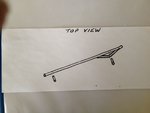
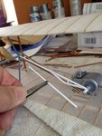
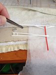
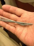
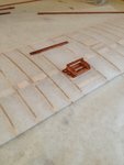
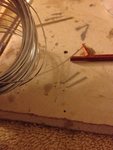
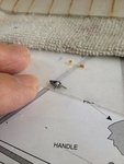
The first two drawings show the main tube itself. This is where it all starts. This is the core. This is the foundation for everything else to be added on. The drawing also shows a short bent piece of tubing was wielded to the main conduit. Wrights added this bent piece of tubing to the main conduit solely for the purpose of reinforcement. The second drawing shows two very short pieces of rods being attached to the main conduit. So, like building a plastic model, at this point, we have four pieces of tubing "glued" together. The main piece, the smaller bent piece "glued" underneath and then two very short pieces added on. The picture of the model shows the main conduit trial-fitted to the engine and propeller support struts with my tweezers holding the next piece to be added on. If you look carefully, you can see that the main conduit only consists of one main tube with a smaller bent piece attached underneath.
The first two drawings show the main tube itself. This is where it all starts. This is the core. This is the foundation for everything else to be added on. The drawing also shows a short bent piece of tubing was wielded to the main conduit. Wrights added this bent piece of tubing to the main conduit solely for the purpose of reinforcement. The second drawing shows two very short pieces of rods being attached to the main conduit. So, like building a plastic model, at this point, we have four pieces of tubing "glued" together. The main piece, the smaller bent piece "glued" underneath and then two very short pieces added on. The picture of the model shows the main conduit trial-fitted to the engine and propeller support struts with my tweezers holding the next piece to be added on. If you look carefully, you can see that the main conduit only consists of one main tube with a smaller bent piece attached underneath.
Attachments

Last edited:
- Thread starter
- #45
Skyediamonds
Staff Sergeant
- 1,362
- May 26, 2018
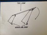
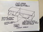
This drawing may require a bit of 'staring" for a few moments. I'm trying to draw the main conduit with its attached bent tube laid down flat on the table with its two very short pieces attached sticking straight up. Then the next part on the bottom of the picture shows the same main conduit as seen looking down from its end. The two very short pieces of tubing are actually "sticking out' at right angles to the conduit assembly. On the right side of the drawing, that "extra" piece sticking out represents the bent tube that is supposed to be attached to the main conduit.
Attachments
- Thread starter
- #46
Skyediamonds
Staff Sergeant
- 1,362
- May 26, 2018
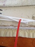
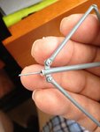
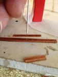
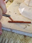
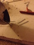
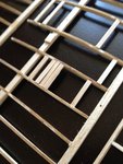
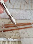
Using the same close up photo as reference, notice that there appears to be a flat piece of metal crossing over the two tubings. This is again, part of the reinforcement. I used a short piece of red-colored tape for this reinforcement. It will be evident how this piece of tape comes into play. Next, I cut to length and glued two pieces of plastic tubing crossed over each other. They are also separated by small thin rods. Looking carefully, at the last small thin rod at the far left of the crossed over tubes, do you see a small piece of plastic sticking out? Notice that the main conduit in the upper portion of the photo and the two crossed over pieces are still separate sub-assemblies.
Attachments
- Thread starter
- #47
Skyediamonds
Staff Sergeant
- 1,362
- May 26, 2018
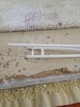
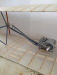
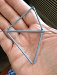
I'm now going to glue the two separate sub-assemblies to the short rods sticking out. I'm laying the main conduit that's above, and moving it down over the crossed members. They will be glued together, yet separated by, the small short rods. The second picture on the right, shows the results after the glue has dried. Can you see how the two sub-assemblies are held together by the two short rods? Keep in mind that the main conduit that's laying on top of the two crossed over tubes below will be used to support the whole assembly by connecting the the propeller shaft struts on one end and the axle of the engine on the other end. See the last picture of the trial fitting and you'll notice that the main conduit is supporting the whole assembly. Next, the whole assembly was painted gloss gray (my own artistic license here). The pieces were then held in my hand for photographic purposes. Notice how that red colored piece of tape is now gray painted & wrapped around? Then trial fitted to the model between the propeller shaft struts and the axle to the engine. Looking carefully, one can easily see that the ends of the main conduit (and its bent reinforcement) are holding up between the propeller strut shafts and the axle of the engine supporting the crossed over tubing "behind" the assembly (that is, in facing forward toward the front of the Flyer).
Attachments
Last edited:
- Thread starter
- #48
Skyediamonds
Staff Sergeant
- 1,362
- May 26, 2018
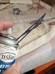
The two propeller shaft struts were made from Evergreen plastruct. They were measured against the two wings, and then cut to size. I then inserted each end into boiling water to soften the plastic. I used a small set of pliers to pinch the ends shut. The ends were then rounded off with a small file & a small hold was drilled through using a pin vise for a small pin to be inserted to simulate the large bolts holding the real assembly together. A piece of piano wire was cut to length and inserted through the main propeller shaft to hold the gear on one end and the propeller on the other end. I added a bit of artistic license here and, like the carburetor, I added a small ring to form a 'lip" to the end of the shaft.
Attachments
- Thread starter
- #49
Skyediamonds
Staff Sergeant
- 1,362
- May 26, 2018
I would like to remind everyone here that Guillow's kit provided all of the accessories in the form of a balsa block for the engine, then small 1/16" square strips of balsa for the propeller shafts. Both drive shafts were from pre-cut laser lite ply. I just decided to play around and take this model to another level of detailing.
- Thread starter
- #50
Skyediamonds
Staff Sergeant
- 1,362
- May 26, 2018
The propeller shaft support struts, along with the drive shafts were fabricated almost at the same time to ensure that they would correctly fit together on the model. Here is the trail fitting of the engine and the propeller shaft struts.
Attachments


- Thread starter
- #51
Skyediamonds
Staff Sergeant
- 1,362
- May 26, 2018
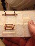
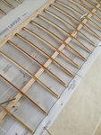
The pilot's cradle was fabricated from scraps of strips of balsa that were sanded smooth, then stained (artistic license) along with some wire to simulate reinforcement of the cradle. Using a photograph as reference, I fabricated the foot rest. I used 1/16" x 1/8" strips of balsa sanded smooth, stained, and assembled together. I've skipped all of the construction of the wings mostly due to many of us have the experience of fabricating such ribs at one time or another. The difference in this case was Guillow's decided to use thread as wire for the trailing edge and that made covering a bit of a challenge.
Attachments
- Thread starter
- #52
Skyediamonds
Staff Sergeant
- 1,362
- May 26, 2018
Next, I'll be happy to post the rigging, starting with the wing-warping. It's here, that the true geniuses of the Wrights really shined. Until then, Skye

SANCER
Senior Master Sergeant
I just returned to your thread and it is a beautiful and dedicated scratch work.
It is very illustrative and explained in a very detailed way. All the wiring to tighten the wings will be a stage that interests me.
Regards.
It is very illustrative and explained in a very detailed way. All the wiring to tighten the wings will be a stage that interests me.
Regards.
- Thread starter
- #55
Skyediamonds
Staff Sergeant
- 1,362
- May 26, 2018
Sancer and Wurger:
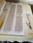
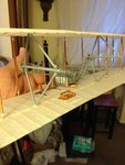
Thank you very much for your responses. I literally reworked my writings about 4-5 times to see if I described my build in a way that would be easy to understand. The crossed-chain drive was one of the more confusing aspects of the Wrights' Flyer and I was hoping I could explain it in good detail. You wouldn't believe how many modelers didn't get it correct, even with the simple plywood cutout provided by Guillow's kit manufacturer. If anyone wishes to try their hand on the Guillow's Wright Bros.' Flyer, I suggest that they have a couple of wooden kit build experiences first. This is a delicate model and not for the faint of heart. I have enclosed a few sample photos of the Flyer during its early stages of the build. As you can see from one of the close up pictures, Guillow's has decided to use thread as the trailing edge of the wings. This is accurate as it was done on the full scale Flyer. However, it poses a couple of challenges for the modeler: 1) the whole frames of both wings are more delicate with more chances of breaking, and 2) it's more challenging to cover the wings. Instead of just first covering the bottom wing and then later cover the top wing as each separate step, the covering must be done in one step with the tissue wrapped around the whole wing at the same time. This is difficult to do trying to work out the winkles of the tissue covering, but with the threads along the trailing edge, it's even a greater challenge. Guillow's to their credit have done a remarkable job in producing a kit of the famous Flyer. I'll start the post on rigging with the wing warping next.
Thank you very much for your responses. I literally reworked my writings about 4-5 times to see if I described my build in a way that would be easy to understand. The crossed-chain drive was one of the more confusing aspects of the Wrights' Flyer and I was hoping I could explain it in good detail. You wouldn't believe how many modelers didn't get it correct, even with the simple plywood cutout provided by Guillow's kit manufacturer. If anyone wishes to try their hand on the Guillow's Wright Bros.' Flyer, I suggest that they have a couple of wooden kit build experiences first. This is a delicate model and not for the faint of heart. I have enclosed a few sample photos of the Flyer during its early stages of the build. As you can see from one of the close up pictures, Guillow's has decided to use thread as the trailing edge of the wings. This is accurate as it was done on the full scale Flyer. However, it poses a couple of challenges for the modeler: 1) the whole frames of both wings are more delicate with more chances of breaking, and 2) it's more challenging to cover the wings. Instead of just first covering the bottom wing and then later cover the top wing as each separate step, the covering must be done in one step with the tissue wrapped around the whole wing at the same time. This is difficult to do trying to work out the winkles of the tissue covering, but with the threads along the trailing edge, it's even a greater challenge. Guillow's to their credit have done a remarkable job in producing a kit of the famous Flyer. I'll start the post on rigging with the wing warping next.
Attachments
Last edited:
- Thread starter
- #56
Skyediamonds
Staff Sergeant
- 1,362
- May 26, 2018
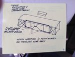
The wing warping: Like the drawings for the crossed chain drives. I thought perhaps it's best if I start off the post with a few drawings describing the function of the wing warping just like the full sized Flyer. This is not difficult and when one studies the concept, it really makes a lot of sense. The Wrights have included a few extra details that were not considered by other inventors or experimenters and I'll explain them each step.
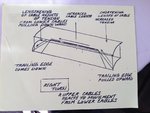
To begin; the drawing shows the wing warping in neutral position. Everything is static. The rigging for the wing warping is only along the trailing edge of both wings. The rigging is a "closed loop" system. That is, when the pilot's cradle is slid in one direction, activating the trailing edge of one side, the rigging also pulls the opposite wing as well. In addition, the rigging also includes pulling the rudder in the direction of the turn. I did not include this fact in this drawing to keep things simple. Finally, you'll notice that the rigging is only at the wingtips. All other forms of rigging were purposely left off so that the wings would be able to twist. If the other riggings were to be included, the wingtips would be too stiff to twist.
To begin; the drawing shows the wing warping in neutral position. Everything is static. The rigging for the wing warping is only along the trailing edge of both wings. The rigging is a "closed loop" system. That is, when the pilot's cradle is slid in one direction, activating the trailing edge of one side, the rigging also pulls the opposite wing as well. In addition, the rigging also includes pulling the rudder in the direction of the turn. I did not include this fact in this drawing to keep things simple. Finally, you'll notice that the rigging is only at the wingtips. All other forms of rigging were purposely left off so that the wings would be able to twist. If the other riggings were to be included, the wingtips would be too stiff to twist.
Attachments
- Thread starter
- #57
Skyediamonds
Staff Sergeant
- 1,362
- May 26, 2018
I'll start with just the lower wing rigging. As can be seen, the lower rigging only pulls the top wing. When the pilot decides to turn to the right, he slides his cradle to the right and thereby pulling the cables of the lower left wing to pull downward the top wing via pulleys.
Attachments
- Thread starter
- #58
Skyediamonds
Staff Sergeant
- 1,362
- May 26, 2018
The top wing rigging is actually dependent upon the lower wing rigging. The rigging to the top wing is reactive. It only acts as a response to the pulls from the lower wing's rigging. This is part of the "closed-loop" system that was copied by many aircraft manufacturers of biplanes and it is still in use today.
Attachments
- Thread starter
- #59
Skyediamonds
Staff Sergeant
- 1,362
- May 26, 2018
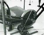
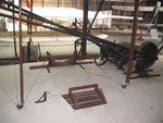
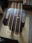
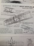
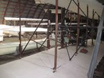
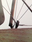
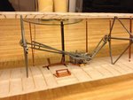
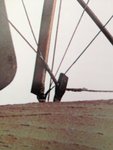
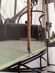
Starting (again) with research: The artist's drawings clearly illustrate the rigging in all of its complexity and its accurate enough that we can see how some of the rigging is left off at the wingtips to allow for twisting. The next picture we can see how the outer wings are rigged. We can see how only the lower wing is rigged to pull downward the top wing. The next photo of the full sized Flyer on display shows a close up of the Wright's pulley used in the system. Finally, the last two pictures show that I purposely left off many of the rear struts that are usually near the center of the Flyer. This was done so I can get my hands inside the model to rig up the wings. When doing a model involving rigging, I've found it's much easier to access to some of the details such as cabane struts near the fuselage that needing rigging when I leave out the outer wing struts that would normally get in my way. To summarize, it's easier to work from the inside to the outside. The same can be said for cockpit interiors of many aircraft as well. For example, we could start with the floor board and rudder pedals and work our way out to the instrument panel and then to the side panels and the control stick and back to the pilot's seat.
Attachments
- Thread starter
- #60
Skyediamonds
Staff Sergeant
- 1,362
- May 26, 2018
Before commencing on the rigging, I needed to have everything ready. I decided to replicate the pulley used on the full sized Wright Flyer. The second picture shows the pulley laid out. I simply cut a strip of plastic and wrapped it around a small cut piece of brass tubing and stuck some pins through for both anchor support and axle to the "pulley" of the brass tubing. Finally, I prepared all of the wing struts by staining them with cherry wood stain (artistic license here again), then giving them a coat of varnish. Afterwards, I wrapped them with thin white threads as seen on the full sized Flyer in the last picture. The threads they used were dark in color and I wanted the threads to "pop out" and give it some contrast against the dark wood stained struts. Finally, each strut was drilled with a pin vise to open the holes wider for the rigging. Guillow's struts already came pre-drilled, but the hole were much too small. Now everything is ready for the rigging of wing warping.
Attachments
Users who are viewing this thread
Total: 1 (members: 0, guests: 1)